


-25-
<:=<B;1BA@
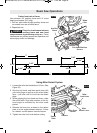
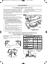
• A “compound cut” is a cross-cut made with the
blade both at a a miter angle and at a bevel angle.
• Because it may take several tries to obtain the
desired compound angle, perform test cuts on
scrap material before making your cut.
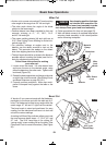
<99<DA52@26;@A?B0A6<;@3<?
:.86;4F<B?0<:=<B;10BA
1. Extend the base extensions and fence. (See
Sliding Fences and Base Extensions on page
20 & 21.)
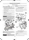
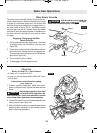
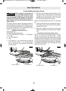
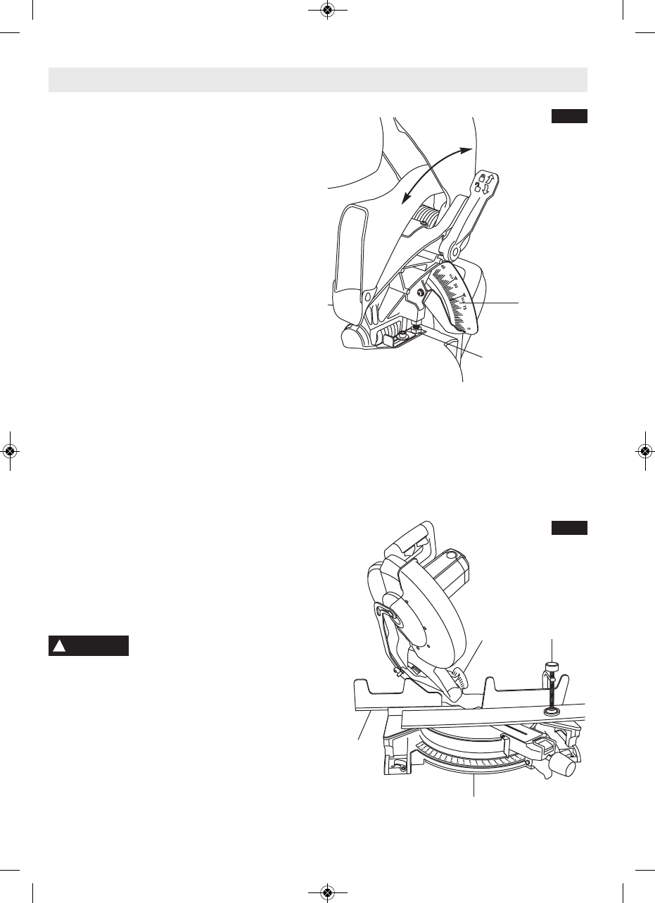
2. Properly position workpiece. Make sure work-
piece is clamped firmly against the table or the
fence(Figure 38).
(@2 09.:=6;4 =<@6A6<; A5.A
1<2@;<A6;A2?32?2D6A5<=2?.
A6<;23<?2@D6A056;4<;9<D2?52.1.@@2:
/9FA<:.82@B?209.:=092.?@4B.?1.;152.1
.@@2:/9F
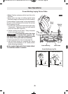
3. Set miter and bevel angles according to the in-
structions on page 24 and 25 for miter and
bevel cuts.
4. Follow the procedures for chop cut.
5. Wait until blade comes to a complete stop be-
fore returning head assembly to the raised po-
sition and / or removing workpiece.
Cutting crown molding flat on the table requires
compound cuts. See cutting crown molding sec-
tion on page, 28 & 29.
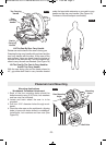
!
WARNING
2C29
&0.92
!.A2?6.9
9.:=
&9616;4
2;02
!6A2?&0.92
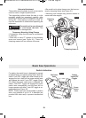
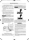
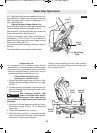
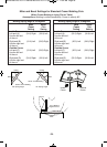
A -2° Right Bevel Stop is also available for back cut-
ting applications. Simply slide this stop forward and
back to engage the 0° stop and disengage for -2°
stop. (See Figure 37)
&2AA6;4A52&.DA<!.822C29BA
Extend the base extension and fence (See Sliding
Fence and Base Extension on page 20 & 21)
With one hand, pull the bevel lock lever forward to
unlock the saw head. (See Figure 37)
Adjust your left bevel stop to one of the three pre-
set locations, – 33.9°, 45° and 47° Left, if desired, tilt
head left until you reach the desired angle on your
bevel scale. (See Figure 37)
Lock the bevel lock by pushing it toward the back of
the saw.
Follow the chop cut procedures in the manual.
<08
H2C29&A<=
%645A
(;9<08
FIG. 37
.@60&.D#=2?.A6<;@
FIG. 38
2C29
&0.92
BM 2610021316 10-11 E:BM 2610021316 10-11 E.qxp 10/17/11 11:02 AM Page 25