


Emerson Process Management GmbH & Co. OHG1-12
X-STREAM X2
Short Form Manual
HASX2E-SFM-HS
02/2012
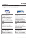
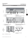
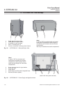
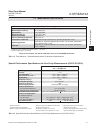
1.5 X-STREAM X2XF Field Housings
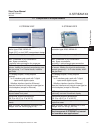
1 Screw-type terminals for signal cables
2 Power line lter
3 Cable glands
4 Power supply terminals with integrated fuses
5 Ethernet connector (option)
Fig. 1-5: X-STREAM XLF - Side and Bottom View
Fig. 1-6: X-STREAM XLF - Power Supply and signal terminals
(shown with front panel removed)
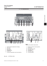
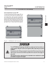
Note!
In case of XXF, the terminals and
connectors are located at the upper
compartment, while physical compo-
nents and gas ttings are in the lower
compartment.
21 3
5 4
5
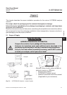
1 Cable gland for power cable
2 Cable glands for signal cables
3 4 brackets for wall-mounting
4 Gas in- & outlets (max. 8)
5 Cutouts, to combine 2 housings (here closed)
Note!
In case of XXF, the cable glands are located
at the upper compartment, while the gas in-
& outlets are at the bottom side of the lower
compartment.
Also only 2 brackets are at each compartment.
1 32 45