


Emerson Process Management GmbH & Co. OHG 2-21
X-STREAM X2
Short Form Manual
HASX2E-SFM-HS
02/2012
2
Installation
2.6 Installation - X-STREAM X2XF Field Housings
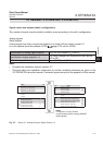
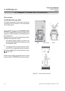
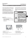
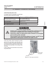
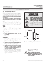
Connecting the power cord
The power cord is connected to screw-type
terminals located inside the housing.
Feed the power cable through the cable
gland at the instrument´s right side and strip
the outer insulation. Strip the individual wires
and connect to the terminals (a label is loca-
ted next to the terminals on the mains lter
housing).
Finally, tighten the outer dome nut to secure
the power cable.
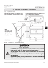
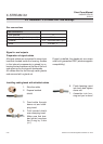
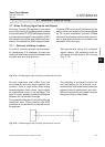
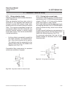
Fig. 2-13: Power supply connections
Live L
Earth PE
Neutral N
Power supply
cable gland
Accepted wire gauge: 0.2…4 mm
2
(AWG 24…AWG 12)
Recommended wire gauge
min. 1.5 mm² (AWG 15),
end sleeves not required
Skinning length: 8 mm (0.315")
Thread: M3
Min. tightening torque: 0.5 Nm (4.4 in.lb)
ELECTRICAL SHOCK HAZARD
Verify the power supply at installation site meets the specication given on
the analyzer´s nameplate label, before installing the instrument!
Verify power cables are disconnected and/or instrument is de-energized
prior to working at the terminals!
Verify the power cord is layed with a distance of at least 1 cm (0.5“) to any
signal cable to ensure proper insulation from signal circuits!