


Emerson Process Management GmbH & Co. OHG 2-11
X-STREAM X2
Short Form Manual
HASX2E-SFM-HS
02/2012
2
Installation
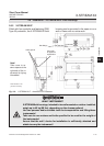
2.6 Installation - X-STREAM X2GK, X-STREAM X2GP
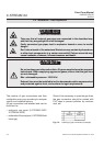
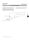
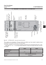
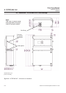
Fig. 2-5: X-STREAM X2GP - rear panel, shown with options
Gas inlets
Gas outlets
Purge gas inlet
(optional)
Analog outputs / NA-
MUR status relays
Modbus interface
(RS 485 / RS 232 /
Modbus 485)
Digital inputs /
outputs
Power in
Fuses
Power switch
Services interface
Strain reliefs and
shielding contacts
for signal cables
4 screw holes for rack mounting
(7.5 x 10.5 mm / 0.29" x 0.41")
RJ45 ethernet connectors
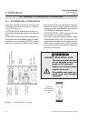
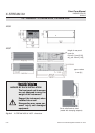
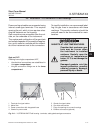
The number and congration of the gas inlets and outlets vary from model to model and are
indicated on the notice on the rear of the instrument.
To simplify installation, we recommend labelling the gas lines as in the Figres above (In1, Out1,
…, In4, Out4 or 1, 2, … 7, 8) .This avoids confusion in case the analyzer ever has to be dis-
connected.
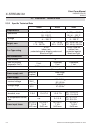
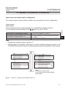
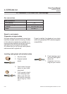
X2GK X2GP
Gas connections
max number 8 8
max for purging (incl. / separate) 2 incl. 1 incl. & 1 separate
material PVDF; stainless steel (opt.)
sizes 6/4 mm;
1
⁄4"
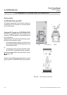
Cover for eO
2
or tO
2
sensor