


Emerson Process Management GmbH & Co. OHG TOC-3
X-STREAM
Short Form Manual
HASX2E-SFM-HS
02/2012
TOC
Table of contents
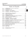
Index of fIgures
Fig. 1-1: X-STREAM Front Panel (here the X-STREAM X2GP)......................1-3
Fig. 1-2: X-STREAM X2GK .................................................1-7
Fig. 1-3: X-STREAM X2GP - Details ..........................................1-9
Fig. 1-4: X-STREAM XLF / XXF- Front Views ..................................1-11
Fig. 1-5: X-STREAM XLF - Side and Bottom View...............................1-12
Fig. 1-6: X-STREAM XLF - Power Supply and Signal Terminals ....................1-12
Fig. 2-1: X-STREAM X2 Analyzers - Scope of Supply .............................2-1
Fig. 2-2: Labelling of Gas Connectors (example) .................................2-6
Fig. 2-3: Installation in Bypass Mode ..........................................2-7
Fig. 2-4: X-STREAM X2GK - Rear Panel ......................................2-10
Fig. 2-5: X-STREAM X2GP - Rear Panel, Terminal Adapters, Side Brackets ..........2-11
Fig. 2-6: X-STREAM X2GK & X2GP - Dimensions...............................2-12
Fig. 2-7: Socket X1 - Analog Outputs & Digital Outputs 1-4 ........................2-13
Fig. 2-8: Power Supply Connectors ..........................................2-14
Fig. 2-9: X-STREAM XLF - Dimensions for Installation...........................2-15
Fig. 2-10: X-STREAM XXF - Dimensions for Installation...........................2-16
Fig. 2-11: X-STREAM X2XF Field Housing - Terminals, Cable Glands, Gas Connectors ..2-17
Fig. 2-12: Terminal Block X1 - Analog Outputs & Digital Outputs 1-4 (XSTA) ...........2-20
Fig. 2-13: Power Supply Connections .........................................2-21
Fig. 2-14: Shielded Signal Cable, Shielding Connected At Both Ends. ................2-23
Fig. 2-15: Shielded Signal Cable, Shielding Connected At One end...................2-23
Fig. 2-16: Signal Cable With Double Shielding, Shieldings Connected At Alternate Ends. .2-24
Fig. 2-17: Shield Connector Terminal With Cable .................................2-24
Fig. 2-18: Suppressor Diode for Inductive Loads. ................................2-25
Fig. 2-19: Driving High-Current Loads .........................................2-25
Fig. 2-20: Loads in Series...................................................2-26
Fig. 2-21: Loads in Parallel..................................................2-26
Fig. 3-1: Leak Testing With U-Turn Manometer ..................................3-2
Fig. 3-2: X-STREAM Front Panel .............................................3-3