


Emerson Process Management GmbH & Co. OHG3-2
X-STREAM X2
Short Form Manual
HASX2E-SFM-HS
02/2012
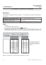
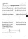
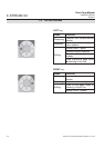
3.1 Performing a Leak Test
Max. pressure 7.25 psig
(500 mbar)!
Multi channel instruments:
Analyzers with parallel tubing
require separate leak tests for
each gas path !
Before starting up the instrument, it appears
to be appropriate to perform a leak test, thus
ensuring the gas path system does not have
leaks, and to achieve best and proper measu-
ring results.
The following procedure describes how to
perform a leak test with focus on the instru-
ment.
The gas path system should be leak tested
at least on a bimonthly basis and after main-
tenance, replacement or repair of gas path
parts.
Note!
It is recommended to include external equip-
ment (e.g. cooler, dust lters, etc.) into a leak
test!
3.1 Performing a Leak Test
Required tools
• U-turn manometer for max. 1.45 psi
(100 mbar)
• Stop valve
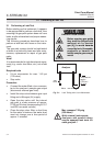
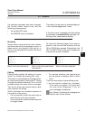
Procedure
• Connect the water lled u-turn manome-
ter to the analyzer‘s sample gas output
(disconnect external gas lines).
• Install the stop valve between gas input
tting and a Nitrogen (N
2
) supply.
• Open the stop valve until the internal
gas path is under pressure of approx.
0.725 psi/50 mbar (corresponding to 19.7
inch/500 mm water column)
• Close the stop valve. After a short time
for the water to balance, the water level
must not change over a time period of
approx. 5 minutes!
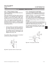
Analyzer
overpressure
approx.
0.725 psi /
50 mbar
stop
valve
Water
Fig. 3-1: Leak Testing with U-turn Manometer
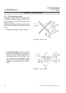
HAZARD FROM GASES
Before opening gas paths
they must be purged with
ambient air or neutral
gas (N
2
) to avoid hazards
caused by toxic, ammable,
explosive or harmful to
health sample gas compo-
nents!