


Emerson Process Management GmbH & Co. OHG 2-17
X-STREAM X2
Short Form Manual
HASX2E-SFM-HS
02/2012
2
Installation
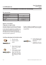
Power and signal cables are connected using
internal screw-type terminals. This requires
opening the unit, which in turn requires relea-
sing the fasteners on the housing.
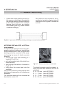
Gas connectors are accessible from the out-
side, on the underside of the instrument.
The number and congration of the gas inlets
and outlets depends on the analytical applica-
tion, and is noted on a sticker on the undersi-
de of the instrument next to the connectors.
To simplify installation, we recommend label-
ling the gas lines in accordance with these
markings. This avoids confusion should the
analyzer need to be disconnected for main-
tenance.
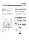
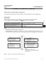
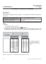
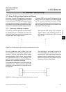
Fig. 2-11: X-STREAM X2XF Field housing - terminals, cable glands and gas connectors
5 Glands for signal cables
6 Gas inlets and outlets
7 Plugs for openings to connect housings
8 Ethernet connectors (optional)
1 Terminals for signal cables
2 Mains lter
3 Power connections with integrated fuses
4 Glands for power cable
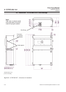
2.6 Installation - X-STREAM X2XF Field Housings
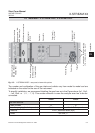
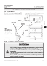
6
5
7
Gas inlets
Gas outlets
18 423
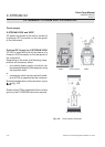
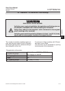
Note on XXF!
Differing from single compartment XLF,
• the electrical connections are established in
the upper compartment,
• the gas connection ttings are at the lower
compartment.
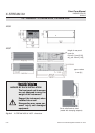
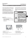
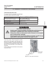
GASKETS AT LOW TEMPERATURES
Consider that enclosure gas-
kets may be frozen when
the instrument is installed
outdoors. Carefully open the
enclosure at temperatures
below -10 °C to not damage the
gaskets.
Damaged gaskets void the
ingress protection, possibly
causing property damage,
personal injury or death.