


Emerson Process Management GmbH & Co. OHG 2-23
X-STREAM X2
Short Form Manual
HASX2E-SFM-HS
02/2012
2
Installation
2.7 Notes On Wiring Signal Inputs and Outputs
2.7 Installation - Notes on Wiring
Emerson Process Managament has made
every effort during the development process
to ensure that the X-STREAM analyzer series
ensures electromagnetic compatibility (EMC)
with respect to emission and interference resi-
stance, as conrmed by EMC measurements.
However, EMC is not wholly inuenced by the
design of the instrument, but to a large degree
by the on-site installation process. Please
observe the following sections and precauti-
ons to guarantee the safe and problem-free
operation of this analyzer.
2.7.1 Electrical shielding of cables
In order to minimise ambient electromagne-
tic interference, it is necessary to take care
making all electrical connections between the
analyzer and any other devices:
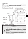
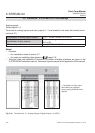
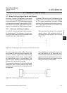
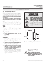
Fig. 2-14: Shielded signal cable, shielding connected at both ends.
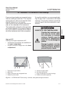
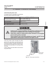
On-site conditions often differ from test
environments and may require special pre-
cautions. Such a case arises when strong
electromagnetic elds which could induce
an interference current in the shielding. This
type of current creates a potential difference
between the connected housings.
Two possible methods of eliminating this are
described here. Fitters familiar with EMC
problems must decide which method should
be emplyed.
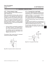
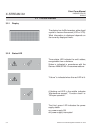
• The shielding is connected only at one
end (connecting to the analyzer is re-
commended): this gives better protection
against external interference, and inter-
ference currents are prevented because
the ground loop is interrupted.
Fig. 2-15: Shielded signal cable, shielding connected at one end.
We recommend using only shielded
signal cables. The shielding must be
connected at both ends to the housing
(Fig. 2-14).