


Emerson Process Management GmbH & Co. OHG2-20
X-STREAM X2
Short Form Manual
HASX2E-SFM-HS
02/2012
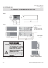
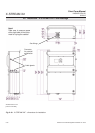
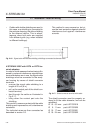
2.6 Installation - X-STREAM X2XF Field Housings
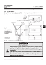
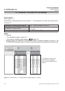
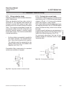
Fig. 2-12: Terminal block X1 - Analog Outputs & Digital Outputs 1-4 (XSTA)
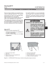
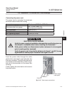
Notes!
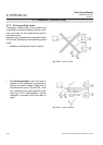
• Consider
• the installation notes in section 2.7
• the notes on installing cable glands on page 2-18.
• Technical data and installation information for further available interfaces are given in the
X-STREAM X2 instruction manual. Connector layouts are part of the appendix of this manual.
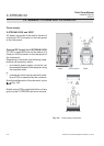
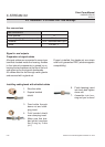
Analog signals
Relay outputs 1-4
Terminals for analog signals and relay outputs 1 - 4 are located on the outer left module (termi-
nal block X1).
**)
Congration of relay output
terminals as per standard
factory setting (NAMUR status
signals)
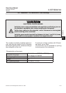
Pin Signal
P2.1 Channel 1, (+) 4 (0) - 20 mA
P2.2 Channel 1, GND
P2.3 Channel 2, (+) 4 (0) - 20 mA
P2.4 Channel 2, GND
P2.5 Channel 3, (+) 4 (0) - 20 mA
P2.6 Channel 3, GND
P2.7 Channel 4, (+) 4 (0) - 20 mA
P2.8 Channel 4, GND
P2.9 Channel 5, (+) 4 (0) - 20 mA
P2.10 Channel 5, GND
P2.11 not used
P2.12 not used
P3.1 not used
P3.2 not used
P3.3 Output 1 (Failure), NC
P3.4 Output 1 (Failure), NO
P3.5 Output 1 (Failure), COM
P3.6 Output 2 (Maintenance Request), NC
P3.7 Output 2 (Maintenance Request), NO
P3.8 Output 2 (Maintenance Request), COM
P3.9 Output 3 (Out of Spec), NC
P3.10 Output 3 (Out of Spec), NO
P3.11 Output 3 (Out of Spec), COM
P3.12 Output 4 (Function check), NC
P4.1 Output 4 (Function check), NO
P4.2 Output 4 (Function check), COM
P4.3 not used
P4.4
P4.5
P4.6
P4.7
P4.8
P4.9
P4.10
P4.11
P4.12
Relay Outputs
**)
Analog Outputs
Serial Interface
*)
Specication of analog signal outputs: 4 (0) – 20 mA; burden: R
B
≤ 500 Ω
Specication of relay outputs:
Dry relay change-over contacts can be used as
NO or NC.
Electrical specication:
max. 30 VDC, 1 A, 30 W