


CHAPTER 2: ELECTRICAL BACKGROUND
EPM 6000 MULTI-FUNCTION POWER METERING SYSTEM – USER GUIDE 2–3
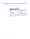
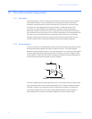
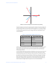
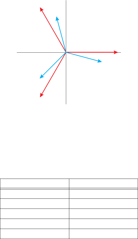
FIGURE 2–2: Three-Phase Voltage and Current Phasors for Wye Winding
The phasor diagram shows the 120° angular separation between the phase voltages. The
phase-to-phase voltage in a balanced three-phase wye system is 1.732 times the phase-
to-neutral voltage. The center point of the wye is tied together and is typically grounded.
The following table indicates the common voltages used in the United States for wye-
connected systems.
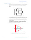
Usually, a wye-connected service will have four wires: three wires for the phases and one
for the neutral. The three-phase wires connect to the three phases. The neutral wire is
typically tied to the ground or center point of the wye (refer to the Three-Phase Wye
Winding diagram above).
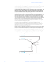
In many industrial applications the facility will be fed with a four-wire wye service but only
three wires will be run to individual loads. The load is then often referred to as a delta-
connected load but the service to the facility is still a wye service; it contains four wires if
you trace the circuit back to its source (usually a transformer). In this type of connection
the phase to ground voltage will be the phase-to-ground voltage indicated in the table
above, even though a neutral or ground wire is not physically present at the load. The
transformer is the best place to determine the circuit connection type because this is a
location where the voltage reference to ground can be conclusively identified.
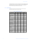
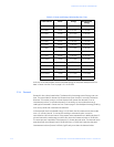
Table 2–1: Common Phase Voltages on Wye Services
Phase-to-Ground Voltage Phase-to-Phase Voltage
120 volts 208 volts
277 volts 480 volts
2400 volts 4160 volts
7200 volts 12470 volts
7620 volts 13200 volts
Van
Vcn
Vbn
Ic
Ib
Ia