5–8 EPM 6000 MULTI-FUNCTION POWER METERING SYSTEM – USER GUIDE
CHAPTER 5: COMMUNICATIONS
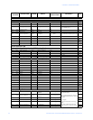
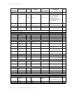
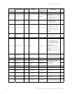
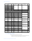
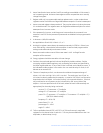
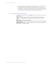
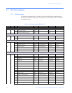
2. Meter Data Section items read as 0 until first readings are available or if the meter is
not in operating mode. Writes to these registers will be accepted but won't actually
change the register.
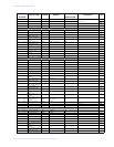
3. Register valid only in programmable settings update mode. In other modes these
registers read as 0 and return an illegal data address exception if a write is attempted.
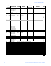
4. Meter command registers always read as 0. They may be written only when the meter
is in a suitable mode. The registers return an illegal data address exception if a write is
attempted in an incorrect mode.
5. If the password is incorrect, a valid response is returned but the command is not
executed. Use 5555 for the password if passwords are disabled in the programmable
settings.
6. M denotes a 1,000,000 multiplier.
7. Not applicable to Shark 100, V-Switch 1, 2, or 3
8. Writing this register causes data to be saved permanently in EEPROM. If there is an
error while saving, a slave device failure exception is returned and programmable
settings mode automatically terminates via reset.
9. Reset commands make no sense if the meter state is LIMP. An illegal function
exception will be returned.
10. Energy registers should be reset after a format change.
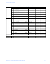
11. Entities to be monitored against limits are identified by Modbus address. Entities
occupying multiple Modbus registers, such as floating point values, are identified by
the lower register addrress. If any of the 8 limits is unused, set its identifier to zero. If
the indicated Modbus register is not used or is a non-sensical entity for limits, it will
behave as an unused limit.
12. There are 2 setpoints per limit, one above and one below the expected range of
values. LM1 is the "too high" limit, LM2 is "too low". The entity goes "out of limit" on
LM1 when its value is greater than the setpoint. It remains "out of limit" until the value
drops below the in threshold. LM2 works similarly, in the opposite direction. If limits in
only one direction are of interest, set the in threshold on the "wrong" side of the
setpoint. Limits are specified as % of full scale, where full scale is automatically set
appropriately for the entity being monitored:
current FS = CT numerator * CT multiplier
voltage FS = PT numerator * PT multiplier
power FS = CT numerator * CT multiplier * PT numerator * PT multiplier * 3 [ *
SQRT(3) for delta hookup]
frequency FS = 60 (or 50)
power factor FS = 1.0
percentage FS = 100.0
angle FS = 180.0
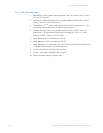
13. THD not available shows 65535 (=0xFFFF) in all THD and harmonic magnitude
registers for the channel when V-switch=4. THD may be unavailable due to low V or I
amplitude, or delta hookup (V only).


