


CHAPTER 2: ELECTRICAL BACKGROUND
EPM 6000 MULTI-FUNCTION POWER METERING SYSTEM – USER GUIDE 2–15
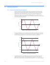
frequency waveforms. These higher frequency waveforms are referred to as harmonics.
The following figure shows the content of the harmonic frequencies that comprise one
cycle of the distorted portion of the above waveform.
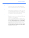
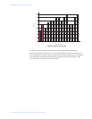
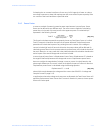
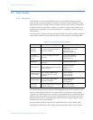
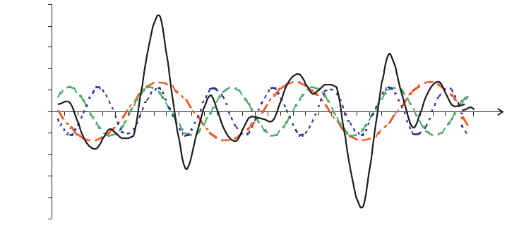
FIGURE 2–12: Harmonics for Distorted Current Waveform
The waveforms above provide an indication of the impact of combining multiple harmonic
frequencies together. The broken lines represent the 3rd, 5th, and 7th current harmonics.
The solid line represents the sum of the three harmonics.
When harmonics are present, it is important to remember that they are operating at
higher frequencies. As such, they do not always respond in the same manner as 60 Hz
values.
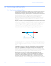
2.5.2 Inductive and Capacitive Impedance
Inductive and capacitive impedance are present in all power systems. We are accustomed
to thinking about these impedances as they perform at 60 Hz. However, these impedances
are subject to frequency variation.
(EQ 2.3)
At 60 Hz, ω = 377; but at 300 Hz (5th harmonic) ω = 1885. As frequency changes, the
impedance changes and system impedance characteristics that are normal at 60 Hz may
be entirely different in the presence of higher order harmonic waves.
Traditionally, the most common harmonics have been the low order odd frequencies, such
as the 3rd, 5th, 7th, and 9th. However newer, new-linear loads are introducing significant
quantities of higher order harmonics.
2.5.3 Voltage and Current Monitoring
Since much voltage monitoring and almost all current monitoring is performed using
instrument transformers, the higher order harmonics are often not visible. Instrument
transformers are designed to pass 60 Hz quantities with high accuracy. These devices,
when designed for accuracy at low frequency, do not pass high frequencies with high
-250
-200
-150
-100
-50
0
50
100
150
200
250
a
Current (amps)
t
X
L
jωL and X
C
1 jωC⁄==