


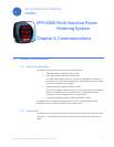

EPM 6000 MULTI-FUNCTION POWER METERING SYSTEM – USER GUIDE 5–1
EPM 6000 Multi-function Power
Metering System
Chapter 5: Communications
GE Consumer & Industrial
Multilin
Communicatio ns
5.1 Modbus Communications
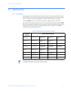
5.1.1 Memory Map Description
The Modbus memory map is divided into four primary sections:
1. Fixed data registers: addresses 0001 to 0021.
2. Meter data registers: addresses 1000 to 5003.
The meter data registers read as “0” until the first readings are available or if
the meter is not in operating mode. Writes to these registers will be accepted
but will have no effect on the register.
3. Command registers: addresses 20000 to 26011.
The command registers always read as “0”. The may be written only when the
meter is in a suitable mode. The registers return an illegal data address
exception if a write is attempted in an incorrect mode.
4. Programmable settings registers: addresses 30000 to 30026.
All registers explicitly listed in the table read as “0”. Writes to these registers will be
accepted but won’t actually the register, since it doesn’t exist.
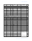
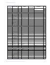
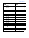
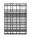
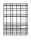
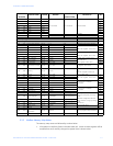
5.1.2 Memory Map
The Modbus memory map is shown below. Additional notes indicated in the memory map
(“See Note ...”) are located at the end of the table, as well as a description of the format
codes.