5–14 EPM 6000 MULTI-FUNCTION POWER METERING SYSTEM – USER GUIDE
CHAPTER 5: COMMUNICATIONS
5.3.4 Application Layer
The application layer contains a header (request or response header, depending on
direction) and data.
Application headers contain the application control field and the function code. For the
application control field, multiple-fragment messages are not allowed for EPM 6000. Each
application header should indicate it is both the first fragment (FIR = 1) as well as the final
fragment (FIN = 1). Application-level confirmation is not used for the EPM 6000.
The following function codes are implemented on the EPM 6000.
• Read (function 1): Objects supporting the READ function are Binary Outputs (object 10),
Counters (object 20), Analog Inputs (object 30), and Class (object 60). These Objects
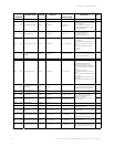
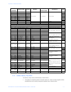
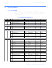
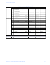
may be read either by requesting a specific variation available as listed in DNP Point
Mapping on page 5–10, or by requesting variation 0. A READ request for variation 0 of
an object will be fulfilled with the variation listed in the DNP points table.
• Write (function 2): The Internal Indications object (object 80), supports the WRITE
function.
• Direct Operate (function 5): The Control Relay Output object (object 12) supports the
DIRECT OPERATE function.
• Direct Operate - No Acknowledgment (function 6): the Change to Modbus RTU
protocol (object 12, point 1) supports the DIRECT OPERATE - NO ACKNOWLEDGMENT
function.
• Response (function 129): Application responses from the EPM 6000 use the RESPONSE
function.


