


308584 13
Installation
Connect the Fluid Hose (continued)
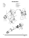
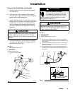
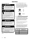
5. Insert the hose (Y) into the hose ferrule housing
(79). See Fig. 5.
6. Push the hose firmly through the fluid inlet tube
(75) until the o-rings on the hose barbed fitting are
seated and the hose bottoms out.
7. Tighten the hose ferrule (77) firmly with a wrench
to about 50 in-lb (5.6 NSm). Pull back on the hose
to make sure it is secure. If not, disconnect the
hose and inspect it for damage. Check the hose
connection periodically for signs that the hose is
loosening.
CAUTION
If the hose comes loose from the fitting, fluid leakage
will occur. Make sure the hose ferrule (77) is tight
and that nothing will pull or catch on the hose during
operation.
8. Connect the other end of the hose to the isolated
fluid supply as instructed in the voltage isolation
system manual. See Fig. 6.
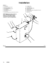
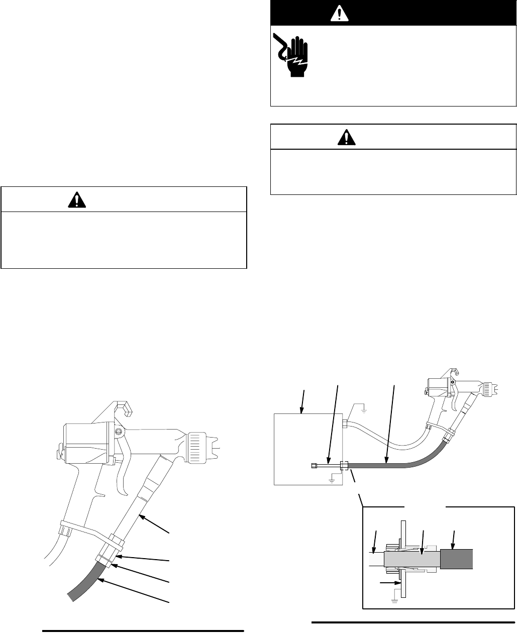
KEY- Fig. 5
Y Graco Waterborne Fluid Hose
75 Fluid Inlet Tube
77 Hose Ferrule
79 Hose Ferrule Housing
Fig. 5
75
77
79
Y
Torque to 50 in-lb (5.6 NSm)
05405B
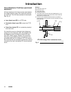
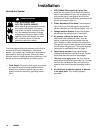
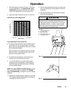
WARNING
ELECTRIC SHOCK HAZARD
To reduce the risk of an electric shock,
the areas of the waterborne fluid hose
that are accessible to personnel during
normal operation must be covered by the outer
hose jacket (H). See Fig. 6.
CAUTION
The Graco warranty is void if the spray gun is con-
nected to a non-Graco voltage isolation system or if
the gun is operated above 60 kV.
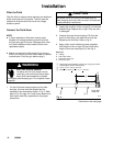
KEY- Fig. 6
H Outer Hose Jacket
K Inner Hose Layer
R Voltage Isolation System Enclosure
Fig. 6
KH
HK
DETAIL
R
H
2
O PRO Voltage Block
connection shown
J
R
The areas of the waterborne fluid hose that are accessible to
personnel during normal operation must be covered by the outer
hose jacket (H).
The portion of the inner hose layer (K) that is not covered by
the outer hose jacket (H) must be inside the voltage isolation
system enclosure (R).
The conductive hose layer (J) must be grounded through its
connection to the isolation system’s grounded safety fence or
enclosure (R).
05149B