


308584 29
Electrical Tests
Test Power Supply Resistance
1. Prepare the gun for service as instructed on
page 30.
2. Remove the power supply (18) from the gun
handle as instructed on page 40.
3. Remove the turbine alternator (37) from the power
supply as instructed on page 41.
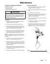
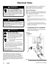
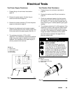
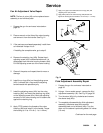
4. Measure the resistance from the power supply’s
ground contact point (B) to the contact spring (18c)
on the other end of the power supply. See Fig. 14.
5. The resistance should be 157.5 to 192.5
megohms. If the resistance is outside the specified
range, the power supply is defective and must be
replaced. If the resistance of the power supply is
correct, proceed to the next test.
03566
Fig. 14
18c 18
B
A
KEY-Fig. 14
A Megohmmeter
B Ground Contact Point
18 Power Supply
18c Contact Spring
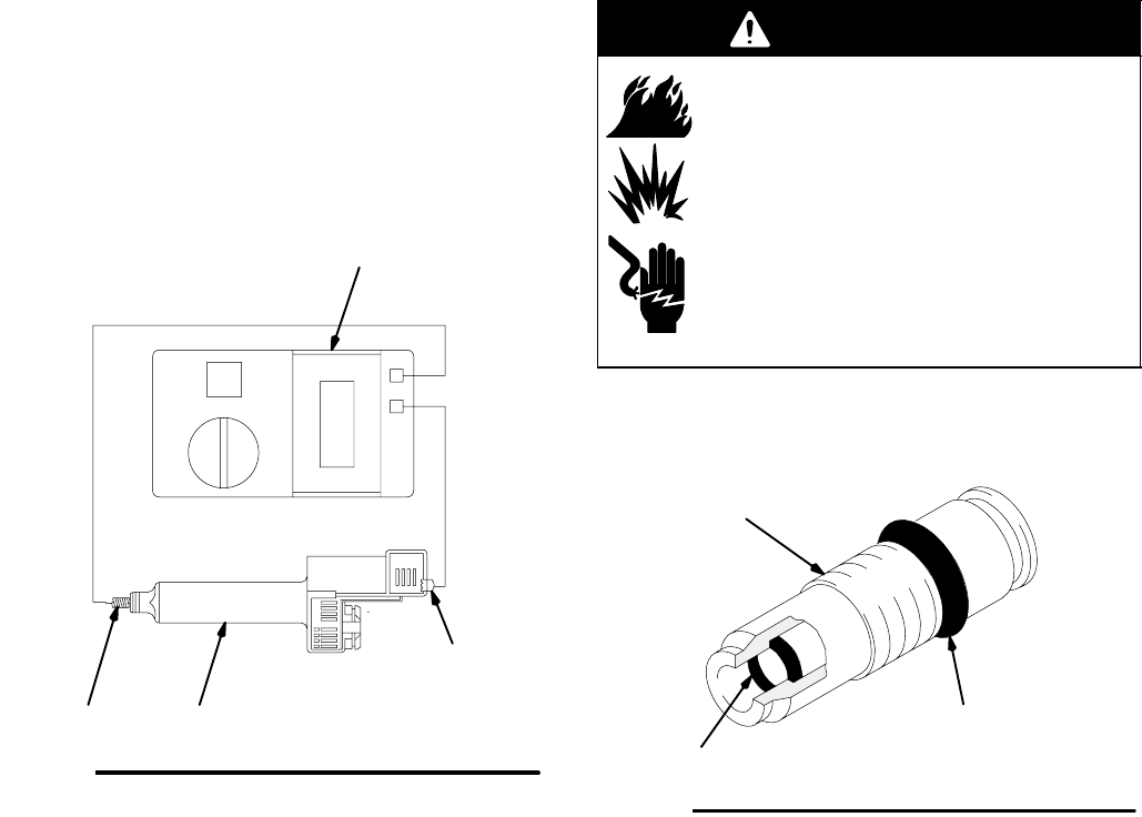
Test Resistor Stud Resistance
1. Prepare the gun for service as instructed on
page 30.
2. Remove the resistor stud (22) as instructed on
page 30.
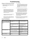
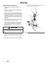
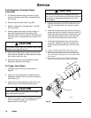
3. Check the resistance between the black resistor
stud contact ring (D) and the needle contact ring
(C). See Fig. 15. You may have to press down on
the contact ring (D) in several places to get a good
reading.
4. The resistance should be 21 to 29 megohms. If the
resistance is correct, make sure the metal contact
in the gun barrel and the needle contact ring (C)
are clean. If the resistance is outside the specified
range, the resistor is defective and the resistor
stud (22) must be replaced. See page 30 to re-
place the resistor stud.
WARNING
FIRE, EXPLOSION, AND ELECTRIC
SHOCK HAZARD
The resistor stud contact ring (D) is a
conductive contact ring, not a sealing
o-ring. See Fig. 15. To reduce the risk of
sparking, which could cause a sparking
or electric shock, do not remove the
resistor stud contact ring (D) or operate
the gun without the contact ring in place.
Do not replace the resistor stud (22) with
anything but a genuine Graco part.
KEY-Fig. 15
C Needle Contact Ring
D Resistor Stud Contact Ring
22 Resistor Stud
Fig. 15
D
C
0442
22