


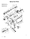
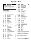
42 308584
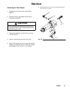
Service
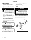
Graco Waterborne Fluid Hose Repair
WARNING
FIRE, EXPLOSION, AND ELECTRIC
SHOCK HAZARD
To reduce the risk of a fire, explosion, or
electric shock:
D Follow the Fluid Voltage Discharge
and Grounding Procedure on page
16 and be sure the ES ON-OFF lever
is turned to OFF before flushing,
checking, or servicing the system and
whenever you are instructed to dis-
charge the voltage.
D Clean all the parts with a non-flammable fluid as
defined on the front cover of this manual.
D Do not service this equipment unless you are
trained and qualified.
D Do not touch the gun nozzle or come within 4
inches (101.6 mm) of the nozzle during gun op-
eration or until after following the Fluid Voltage
Discharge and Grounding Procedure..
WARNING
PRESSURIZED EQUIPMENT HAZARD
To reduce the risk of an injury, follow the Pressure
Relief Procedure on page 16 before checking or
servicing any part of the system and whenever you
are instructed to relieve the pressure.
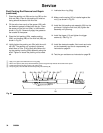
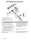
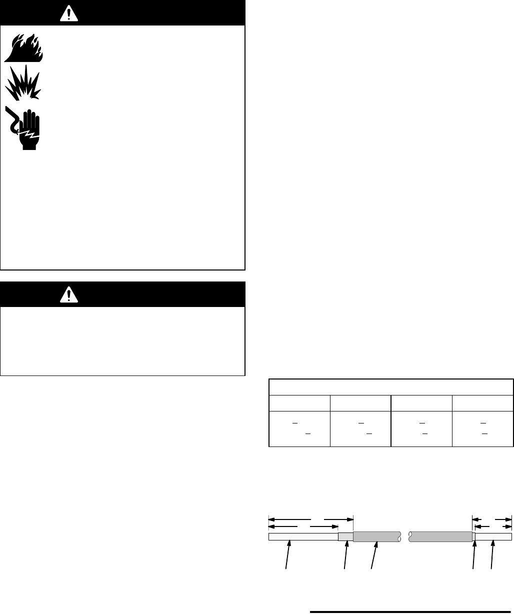
Damaged hoses or hoses that have a “pin-hole” dielec-
tric failure, close to the end of the hose, can be re-
paired by cutting away the failed portion and restrip-
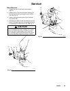
ping the hoses to the dimensions shown in Fig. 29.
1. Discharge the voltage as instructed on page 16.
2. Relieve the system pressure as instructed on page
16.
3. Disconnect the fluid hose from the gun and voltage
isolation system.
4. Cut off the damaged end of the hose. If the hose
has a pin-hole failure, strip back the outer hose
jacket (H) and the conductive layer (J) about 12
inches (105 mm) on each hose end. Look for the
failure point, which will be a very small pin-hole,
discolored due to arcing. Continue stripping back
the hose until the failure point is found.
5. Carefully cut through the outer hose jacket (H) and
peel it back about 12 inches (105 mm). Do not cut
into the conductive layer (J) of the hose.
6. Cut through the first 1/2 inch (12.7 mm) of the
conductive hose layer (J) to create an edge to hold
onto. Peel back the conductive hose layer by
unwrapping it in a spiral pattern. Cut it off at the
dimension shown in Fig. 29.
7. Cut off the inner hose layer (K) to the dimension
shown in Fig. 29.
8. Inspect the hose for any nicks or cuts. Any nicks
or cuts into the inner hose layer (K) will weaken
the dielectric strength of the hose and shorten the
service life. Repeat the above procedure if any
damage is found.
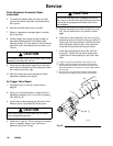
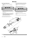
9. Install a new barbed fitting by applying red dielec-
tric grease to the outside of the barbs, and press-
ing the fitting into the gun end of the hose. Refer to
the drawing of the Waterborne Fluid Hose Assem-
bly on page 48.
10. Install the three o-rings on the barbed fitting.
11. Connect the fluid hose to the gun as instructed on
page 12.
Measurements, inches (mm)
A* B* C D
7.75 + 0.1
(196.85 +
2.5)
9.375 + 0.1
(238.13 +
2.5)
4.075 + 0.1
(103.5 + 2.5)
4.375 + 0.1
(111.1 + 2.5)
* The measurements specified are for use with the Graco
H
2
O PRO Voltage Block isolation system.
Fig. 29
H
JK
05180
A
B
D
Isolation System End Spray Gun End
J K
C