page 170 008-0671-00
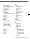
OVLD
message
AC/AC-LVDT Input channel 95
High-Level Input channel 122
Strain-Gage Input channel 77
percentage of Analog-to-Digital converter input 20
symbols 20
track, peak or valley 20
units of measure
AC/AC-LVDT Input channel 85
High-Level Input channel 111
Mathematics Virtual channel 147
Strain-Gage Input channel 65
when shunt calibration resistor applied 21
DOWN button 23
E
EMI/RFI interference
AC/AC-LVDT Input channel 95
DAC Output channel 136
High-Level Input channel 122
Strain-Gage Input channel 78
ENTER button 23
error messages 151
ERROR mode 22
excitation
Strain-Gage Input channel 69
EXIT button 23
F
frequency response
AC/AC-LVDT Input channel 83
High-Level Input channel 109
Strain-Gage Input channel 63
fuse replacement
of SC1000 and SC2000 30
of SC2001 32
of SC3004 34
H
High-Level Input channel 97
2-Point Known Load Calibration 113, 115, 117
3-Point Known Load Calibration 113, 115, 117
5-Point Known Load Calibration 113–114, 116, 118
Analog Output 119–122
auto-zero function 109
Auxilliary Function pins 112, 122
calibration procedure 107
calibration types comparison 113
display setup 111
EMI/RFI interference 122
frequency response 109
OVLD
message 122
remote control of Track/Hold, Peak/Valley clear,
Peak/Valley hold or Tare 112, 122
resolution 109
SETUP menu 109
Shunt Calibration 21, 113, 115, 117
software revision 120
specifications 108
step response time 109
troubleshooting 122
wiring 98
I
indicator lights
limits 54
lower line display of 51
Tare 21
INITIALIZE mode 19
installation of channels 42
L
LEDs. See indicator lights.
lights. See indicator lights.
limits
clearing latched limits 20
enabling 55
indicator lights
latching 57
Limits 01-04 54, 123
Limits 05-08 54, 123
Limits 09-12 54, 123
Limits 13-16 54, 123
open-collector outputs 38
operation 54–55, 57
Relay Output channels 54
scan time 54
SETUP menu 55
wiring 36
LVDT Input channel
See AC/AC-LVDT Input channel
M
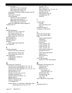
Mathematics Virtual channel 143
display setup 147
operation 145
SensoCode 143
part number 146
viewing program 146
SETUP menu 146
troubleshooting 149
user values 146
wiring 144
menu. See SETUP menu mode.
O
operating modes 19


