SC Series Instruction Manual page 83
AC/AC-LVDT Input Channel11
11.5 Channel Menu
Each AC/AC-LVDT Input channel is configured and calibrated via its channel
menu. Detailed instructions on operating the instrument in the SETUP Menu
mode can be found in “SETUP Menu mode” on page 23. A diagram of all menus
is located in “Setup Menu Reference” on page 157.
11.5.1
OPERATION
Sub-Menu
This menu controls the operation of this channel when the instrument is in the
RUN mode.
AUTO-ZERO
Menu Item
This enables or disables the channel’s automatic zeroing function. When
enabled, the channel will reset its tracking value to zero when the tracking value is
less than 10 display counts for a period of 10 seconds. This removes the effect of
slight temperature shifts in the transducer’s output.
The two options for this menu item are “ON” and “OFF”.
FREQ. RESPONSE
Menu Item
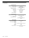
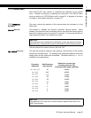
This sets the frequency response, step response, and resolution of the channel
according to the table below. The tracking value, peak/valley detector values and
analog output on this channel are all affected. The default value of
016. HERTZ
is
suitable for most applications.
NOTICE
To compensate for the transducer’s initial warm-up shift, the auto-zero function
operates every 2 seconds during the first 60 seconds of RUN mode operation.
Frequency
Response
Step Response
(ms) (typical)
Resolution (counts) (not
including minimum 10%
overrange/underrange capability)
002. HERTZ/FAST
40 ±25000
002. HERTZ
440 ±25000
008. HERTZ
110 ±15000
016. HERTZ
55 ±10000
032. HERTZ
28 ±10000
050. HERTZ
16 ±5000
100. HERTZ
8 ±5000
250. HERTZ
3 ±2000
500. HERTZ
2 ±2000
800. HERTZ
2 ±2000
NOTICE
Your particular LVDT may have a lower frequency response than the AC-AC
LVDT Input channel.


