page 30 008-0608-00
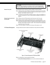
boards in the instrument.
• The Front Panel/Display Board Assembly contains the display and all front panel
controls.
•The Power Supply Board contains the +15V, -15V and +5V power supplies.
•The Microprocessor Board contains the microprocessor, ROM software storage
chip, and the System connector.
•The Hardware Input/Output Channel Boards plug into the remaining four slots
of the SensoBus Backplane Board.
4.3.9 Cleaning
Turn off the instrument and unplug all connectors. Use a soft cloth or tissue and a
mild cleaner. Do not use liquid or aerosol cleaners. Do not allow any cleaner inside
the instrument.
4.3.10 Vehicle Power
Option
Model SC1000 and SC2000 instruments are available with a vehicle power option for
operation with batteries and linear DC power supplies. See “Specifications” on
page 26 voltage and power requirements.
4.3.11 Fuse
Replacement
The power-line fuses of AC-powered instruments are located within the instrument's
power entry module on the rear panel. Use two 2A, 250V fast-blow fuses (p/n 029-
3026-00).
NOTICE
Due to the momentary startup inrush current of the instrument’s power supply,
the use of switching power supplies with the SC are not recommended.


