page 38 008-0608-00
5.4 Limit Output Pins
5.4.1 Overview
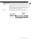
An open-collector output is a transistor logic output that can be used to control DC
loads, drive opto-isolators or relays, or interface directly to logic circuitry. They act very
much like switches: low resistance when turned on and high resistance when turned
off. You can use them as you would a dry relay contact, with the following restrictions:
• The voltage applied must be DC
• The polarity of the DC voltage must be observed
• Maximum voltage: 50VDC
• Maximum power: 2.0W
When Limits 1, 2, 3, or 4 are activated, the corresponding open-collector Limit Output
pin on the System connector will be connected to the DGND (Digital Ground) pin.
However, a SensoCode program running on a Mathematics Virtual Channel may over-
ride this behavior. Consult the Customer Information Sheet included with your instru-
ment for details.
5.4.2 Example
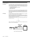
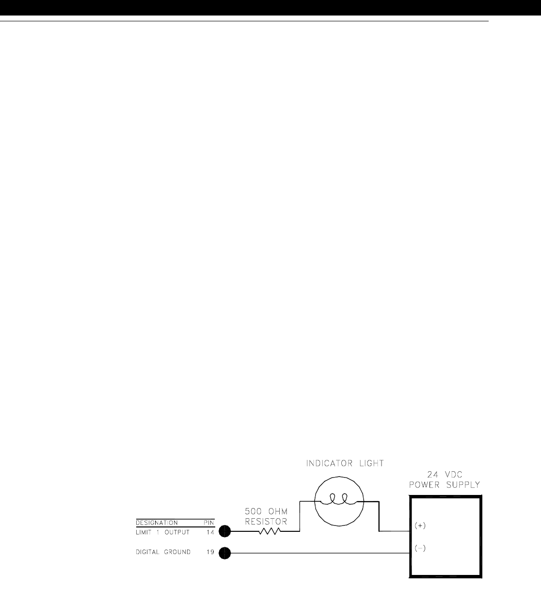
For example, assume that a remote indicator is to be lighted when Limit 1 is activated.
An external 24 VDC power supply connects to the indicator.
When Limit 1 is deactivated, there is high resistance between the Limit 1 Output pin
and the DGND (Digital Ground) pin; little current flows in the circuit and the light is off.
When Limit 1 is activated, there is low resistance between the Limit 1 Output pin and
the DGND (Digital Ground) pin; the light turns on.
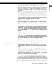
The resistor limits the current flowing in the circuit when the light is lighted to 48 mA.
According to Ohm’s Law:
Lights or other indicators have voltage, current, and/or power ratings that must be
observed in order to avoid damaging them.
Figure 5-2: Open-Collector Output Example
I
V
R
---
=
48mA
24V
500Ω
-------------
=


