page 42 008-0608-00
6.2.4
INSTALL CHANNEL
Menu Item
This menu item will add an Input, Output or Virtual channel as the next highest chan-
nel number in the system.
Input or Output Channel
Installation Procedure
Before installing an Input or Output card, make certain that you know the “card type”
(a two-digit hexadecimal number) of the card you wish to install.
Use the following procedure to install an Input or Output card:
1) When the instrument is in the RUN mode, use the [ENTER] button to change
which channel the display is monitoring. Note the highest channel number that is
presently installed. The new circuit card for the new channel will be installed as
the next channel number.
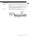
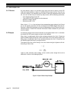
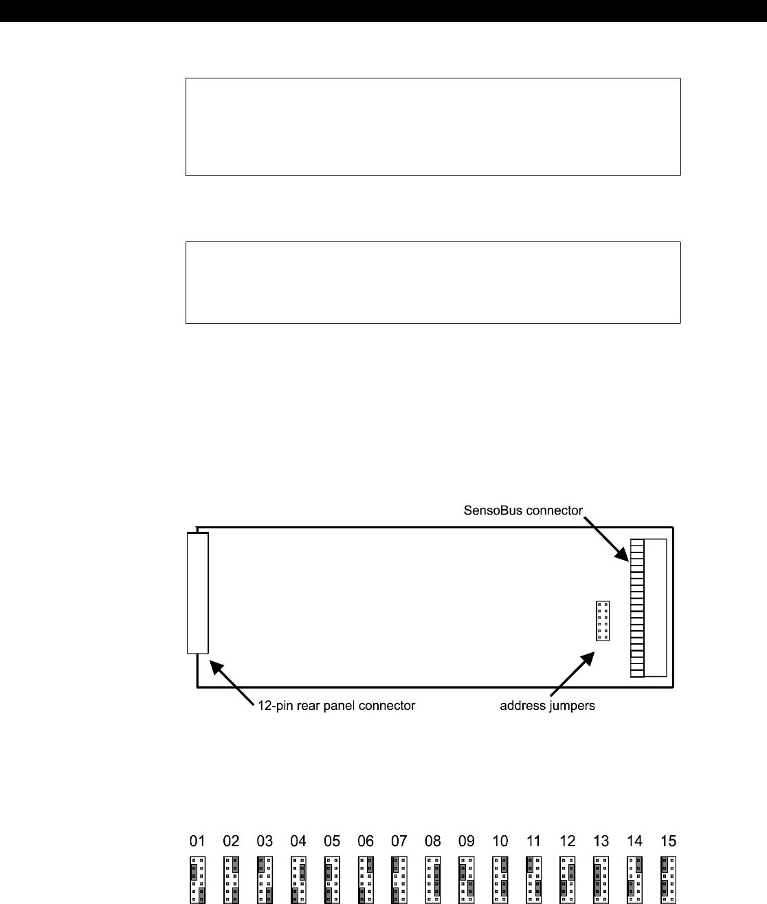
2) Examine the circuit card to be installed and orient it as shown below. On it you
will find the address jumper block.
Figure 6-1: Address Jumper Block Location
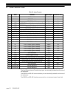
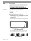
3) Change both address jumpers to match the next available channel in the
instrument according to the chart below. Do not skip any channel numbers.
Figure 6-2: Address Jumper Settings
NOTICE
Installing a channel will cause it to use the “default” or “empty” configuration
information for that channel. All other channels are unaffected.
Any calibration data, SensoCode mathematics programs, display setup,
or other information for that channel will be erased to default values.
CAUTION
Use Electrostatic Discharge (ESD) precautions when unpacking and handling
circuit boards.
Failure to comply with these instructions may result in product damage.


