


Return to Section TOC Return to Section TOC Return to Section TOC Return to Section TOC
Return to Master TOC Return to Master TOC Return to Master TOC Return to Master TOC
A-4
INSTALLATION
DH-10
A-4
SAFETY PRECAUTIONS
INSTALLATION OF THE DH-10
BOOM MOUNT WIRE FEEDER
COMPONENTS
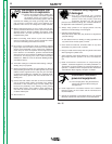
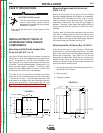
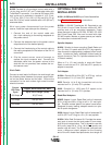
Mounting the DH Double Header Wire
Drive Unit (K1497-1 or -2)
Mount the DH wire drive unit to the boom or structure
using the four 5/16-18 threaded mounting holes locat-
ed on the bottom of the DH drive connection box.
See Figure A.1 for the size and location of the mount-
ing holes. The feed plate assembly is electrically “hot
”
when the gun trigger is pressed. Therefore, make
certain the feed plate does not come in contact with
the structure on which the unit is mounted.
The wire drive unit should be mounted so that the
drive rolls are in a vertical plane so dirt will not collect
in the drive roll area. Pivot the feed plate so it will
point down at an angle so the wire feed gun cable will
not be bent sharply as it comes from the unit. See
Procedure for setting angle of Feed Plate
in the
Operation
section of this manual.
Mounting Single Head Wire Drive Unit
(K679-1 or -2)
Mount the wire feed unit by means of the insulated
mounting bracket attached to the bottom of the gearbox.
Reference L9777 (included with Drive unit) to find the
size and location of the mounting holes. The gearbox
assembly is electrically “hot” when the gun trigger is
pressed. Therefore, make certain the gearbox does not
come in contact with the structure on which the unit is
mounted.
The wire feed unit should be mounted so that the drive
rolls are in a vertical plane so dirt will not collect in the
drive roll area. Position the mechanism so it will point
down at about a 45° angle so the wire feed gun cable will
not be bent sharply as it comes from the unit.
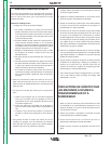
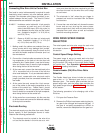
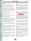
Mounting the DH-10 Control Box (K1496-1)
The same control box is used for both a DH double
header drive, or up to two single head drives. The back
plate of the control box has two keyhole slots and one
bottom slot for mounting. See Figure A.2 for the size
and location of these slots. Mount the box at some con-
venient location close to the wire drive unit which will
enable the desired control cable to reach between the
control box and the wire drive unit.
1. Drill the required holes in the mounting surface, par-
tially install 1/4-20 screws.
2. Mount the box.
3. Tighten the screws.
ELECTRIC SHOCK can kill.
• Turn the input power off at the power
source disconnect switch before
attempting to connect the input power
to the DH-10 Control.
• Only qualified personnel should perform this
installation.
----------------------------------------------------------------------------------------
WARNING
FIGURE A.1
5/16-18 THREAD
2.25
FEED PLATE
DOOR OPEN
5.00
10.50
18.50
3.00
6.00
11.00
BOTTOM FRONT
FIGURE A.2
CLEARANCE
FOR 1/4 BOLT
2.63
12.75
14.50
13.75
5.25
CLEARANCE
FOR 1/4 BOLT
10.50
.50
10.00
2.63
14.00