


Return to Section TOC Return to Section TOC Return to Section TOC Return to Section TOC
Return to Master TOC Return to Master TOC Return to Master TOC Return to Master TOC
B-7
OPERATION
B-7
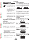
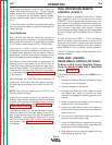
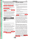
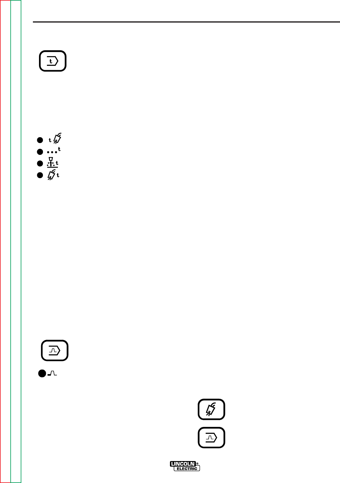
Display Control Keys
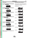
Timer Select key - enables operator to
choose burnback, spot or gas timers, as
indicated by the appropriate light.
Pressing the key causes lights to
sequence (top to bottom, then all off) starting from the
current indicated selection.
When a timer is selected the Voltage display shows
the time setting in seconds, as indicated by “SEC” dis-
played on the speed display. The times are set using
the Voltage encoder knob.
Top Light - indicates preflow time
is being displayed, settable 0.0 to
2.5 seconds (0.2 sec as shipped).
This is the time the shielding gas
flows before the wire feed and
power source are activated.
Second Light - indicates spot time is being displayed,
settable 0.0 (as shipped) to 199.9 seconds.
Third Light - indicates burnback time is being dis-
played, settable 0.00 (as shipped) to 0.25 seconds.
This is the time the arc power is delayed at the stop of
the weld, and should be set to the lowest time
required to prevent the wire sticking in the weld.
Bottom Light - indicates postflow time is being dis-
played, settable 0.0 to 10.0 seconds (0.5 sec as
shipped).
This is the time the shielding gas flows after the wire
feed and power source are deactivated.
Pressing Timer Select Key again, or closing the gun
trigger, shuts all timer lights off, indicating weld
Voltage and Wire Feed Speed are again being dis-
played, and set by the appropriate encoder knob.
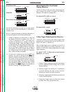
Control Select key - enables
operator to choose Run-In
procedure as indicated by the light
turning on. When light is on, the
settings of Run-In Wire Feed
Speed and Voltage are displayed.
After Weld procedure is set, Run-
in procedure should be set to
optimize arc starting.
Speed encoder knob can adjust run-in speed between
min. rated speed and up to the procedure Weld speed
setting. Run-in speed setting can not exceed Weld
speed setting. Run-in speed setting of 100 IPM or less
is recommended for optimum starting. Factory setting
is near min. rated speed.
DH-10
TIMER
BURNBACK
SPOT
PREFLOW
1
2
POSTFLOW
CONTROL
VOLTS / WFS
RUN-IN
If set below minimum rated speed “---” will show on
the WFS display, indicating Run-in speed is set to
match weld speed setting.
The Run-in (strike) voltage can be set above or below
the Weld voltage setting up to a max of 60 V. If set
below a min of 10 V, the Run-In (strike) voltage dis-
play shows “---”, indicating the Run-In Voltage is set to
match the weld voltage setting. Also, the difference
between Run-in voltage and Weld voltage settings is
maintained automatically if the Weld voltage setting is
changed, so the run-in voltage encoder knob does not
need to be changed to follow the Weld voltage setting.
When trigger is closed (and preflow time is over) the
wire feeds at Run-In speed and volts until the welding
arc strikes, which causes the feed speed and volts to
change to Weld settings.
If the arc does not strike within about 2 seconds, the
Run-In speed automatically changes to Weld speed to
permit “Hot” feeding at higher speed setting for load-
ing wire.
Pressing control key again, or closing the gun trigger,
shuts off light indicating knob settings and displays
are returned to Weld Voltage and Wire Feed Speed.
Digital “Memory” Voltmeter
When the welding gun trigger is activated, the top DH-
10 display reads actual welding voltage from 0.0 to
60.0 VDC with automatic polarity indication for posi-
tive (+) or negative (-) electrode.
If actual voltage drops below 8.0 volts for over 0.8 sec
when the trigger is closed, Loss of Voltage Sense
Shutdown will occur. See “Loss of Voltage Sense
Shutdown” in this section.
The last welding voltage monitored at the end of the
weld is displayed for 5 seconds after the weld has
stopped, as indicated by a 5 second “blinking” display.
This allows checking actual weld voltage after weld
has stopped.
Any keypad or trigger operation will interrupt the 5
second memory display.
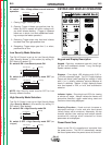
Acceleration Selection
To provide optimum starting of various
processes and procedures, the wire
feed acceleration of the DH-10 can be
set to five levels; 1 thru 5, for each feed-
er and procedure. 1 is the slowest
acceleration and 5 is the fastest.
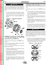
GAS PURGE
CONTROL