


Return to Section TOC Return to Section TOC Return to Section TOC Return to Section TOC
Return to Master TOC Return to Master TOC Return to Master TOC Return to Master TOC
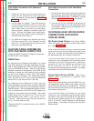
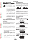
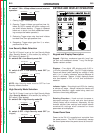
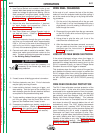
Pulse Power 500:
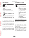
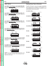
V300 PRO:
Other Power Source Independent:
Set the DIP switches as shown for all other power
sources which can be controlled with a 10KΩ poten-
tiometer circuit.
All DH-10 features operate as described elsewhere in
this manual except for the following differences:
1. Instead of displaying a preset value in volts, the
top display will show a number from “0.00” to
“10.00” in increments of “0.02”. The number can
be used for setting run-in “voltage” as well as
“weld preset voltage”. When the trigger is closed
or while welding, the top display will display actu-
al arc voltage. The voltage displayed while weld-
ing can be used to determine the arc voltage to
be expected for a given number setting. Actual
arc voltage display will still flash for 5 seconds
after a weld has been completed.
2. If a loss of arc voltage occurs, wire will NOT stop
feeding. The Loss of Voltage Sense Shutdown
feature is disabled to permit the use of the DH-10
with power source connections that do not con-
nect the work voltage back to the DH-10 through
the input power cable. The actual weld voltage
while welding will NOT properly be shown on the
top display if the work voltage is not available to
the DH-10 through the input power cable.
B-4
OPERATION
B-4
DH-10
Security
Pwr Sources
M 4
S1
ON
S1
1 2 3 4 5 6 7 8
Security
Pwr Sources
M 4
S1
ON
S1
1 2 3 4 5 6 7 8
Security
Pwr Sources
M 4
S1
ON
S1
1 2 3 4 5 6 7 8
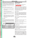
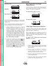
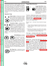
Metric/English Wire Feed Speed
Display Selection
The DH-10 Control is set up for Wire Feed Speed dis-
play in Metric units (m/min) or English units (IPM) by
setting S1 DIP switch 6 (Labeled “M”):
S1 switch 6 OFF = IPM (as shipped)
S1 switch 6 ON = m/min
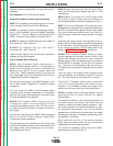
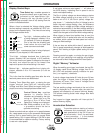
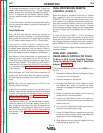
4-Step Trigger Mode Operation Selection
The DH-10 Control is set up for 4-Step Trigger mode
operation with or without weld current interlock by set-
ting S1 DIP switch 7 (Labeled “4”).
When 4-Step trigger mode is selected on the DH-10
keypad (See Keypad and Display Operation in this
section) S1 DIP switch setting determines the 4-step
trigger operation:
S1 switch 7 OFF = 4-Step with current interlock
operation: (As shipped)
1. Closing Trigger initiates gas preflow time followed
by Run-in speed and strike voltage until arc strike
initiates welding.
2. Opening Trigger after welding arc is established
continues welding with weld current interlock.
(Breaking arc stops the feeder operation).
3. Reclosing Trigger continues welding but shuts off
current interlock function.
4. Reopening Trigger stops wire feed and initiates
burnback time, then gas postflow time.
Security
Pwr Sources
M 4
S1
ON
S1
1 2 3 4 5 6 7 8
Security
Pwr Sources
M 4
S1
ON
S1
1 2 3 4 5 6 7 8
Security
Pwr Sources
M 4
S1
ON
S1
1 2 3 4 5 6 7 8