


E-4
THEORY OF OPERATION
DH-10
E-4
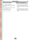
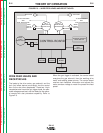
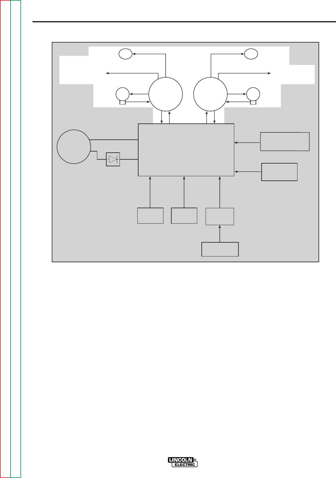
WIRE FEED HEADS AND
RECEPTACLES
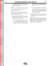
The leads to the drive motor, gas solenoid, and the
tach (hall effect device) are brought into the control
box via the wire drive receptacles. These two 14-pin
receptacles also house the gun trigger leads, the elec-
trode voltage sense lead, and the leads for the option-
al remote with dual procedure capability. Refer to
Figure E.3.
When the gun trigger is activated, the control board
energizes the gas solenoid, then the welding drive
motor and welding power source. The control board
receives tach feedback information and adjusts the
motor armature voltage to match the preset wire feed
speed.
Return to Section TOC Return to Section TOC Return to Section TOC Return to Section TOC
Return to Master TOC Return to Master TOC Return to Master TOC Return to Master TOC
FIGURE E.3 — WIRE FEED HEADS AND RECEPTACLES.
CONTROL BOARD
VOLTS
ENCODER
WFS
ENCODER
INPUT
CABLE
RECEPTACLE
RIGHT
WIRE DRIVE
RECEPTACLE
LEFT
WIRE DRIVE
RECEPTACLE
TO GUN TRIGGER
AND
DUAL PROCEDURE
TO GUN TRIGGER
AND
DUAL PROCEDURE
WIRE
DRIVE
MOTOR
WIRE
DRIVE
MOTOR
DISPLAY
BOARD
CURRENT SENSING
REED SWITCH
GROUND
LEAD
PROTECTOR
KEYPAD
SOLENOID
TACH FEEDBACK
42VDC
TACH FEEDBACK
SOLENOID