


Return to Section TOC Return to Section TOC Return to Section TOC Return to Section TOC
Return to Master TOC Return to Master TOC Return to Master TOC Return to Master TOC
B-5
OPERATION
B-5
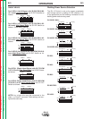
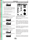
S1 switch 7 ON = 4-Step without current interlock
operation:
1. Closing Trigger initiates gas flow.
2. Opening Trigger initiates gas preflow timer fol-
lowed by Run-in speed and strike voltage until
arc strike initiates welding. (Trigger is released
before arc is struck, but once established break-
ing arc stops the feeder operation).
3. Reclosing Trigger stops wire feed and initiates
burnback time, then gas postflow time.
4. Reopening Trigger stops gas flow if, or when,
postflow time is over.
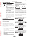
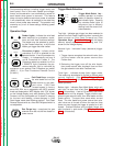
Low Security Mode Selection
The DH-10 Control is set up for Low Security Mode
(See “Security Modes” in this section) by setting S1
DIP Switch 8 (Labeled “S”):
S1 switch 8 ON = Low Security mode ON
S1 switch 8 OFF = Low Security mode OFF (as
shipped)
NOTE: High Security mode must be OFF for Low
Security mode to function.
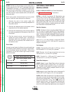
High Security Mode Selection
The DH-10 Control is set up for High Security Mode
(See
Security Modes
in this section) by setting S1
DIP switch 5 (Not labeled):
S1 switch 5 ON = High Security mode ON
S1 switch 5 OFF = High Security mode OFF (as
shipped)
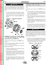
DH-10
Security
Pwr Sources
M 4
S1
ON
S1
1 2 3 4 5 6 7 8
Security
Pwr Sources
M 4
S1
ON
S1
1 2 3 4 5 6 7 8
Security
Pwr Sources
M 4
S1
ON
S1
1 2 3 4 5 6 7 8
Security
Pwr Sources
M 4
S1
ON
S1
1 2 3 4 5 6 7 8
Security
Pwr Sources
M 4
S1
ON
S1
1 2 3 4 5 6 7 8
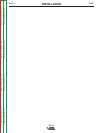
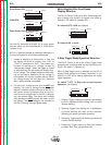
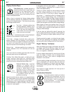
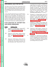
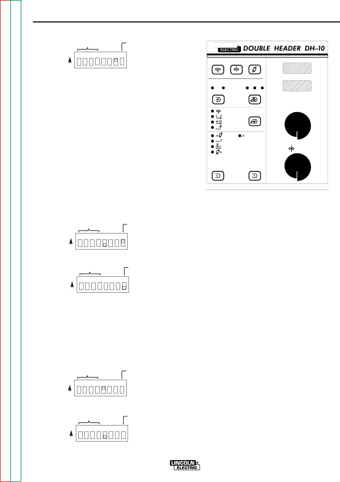
Keypad and Display Description
Keypad - Eight key, membrane type with “snap” tac-
tile feel and embossed domes. Long life design.
Spatter resistant surface.
Displays - Two digital LED displays with 0.56 in.
(14.2 mm) character height. Top (3-1/2 digit) displays
Preset and Actual (while welding) arc voltage in volts
with (+) or (-) polarity indicators, and also displays all
timers in seconds. Bottom (4 digit) displays preset
wire feed speed in IPM, or m/m, and acceleration
selection.
Indicator Lights - Extra bright red LEDs for viewing
at almost any angle. Always indicate the feeder and
procedure selected, trigger mode being used and
function or timer being displayed.
Rotating Encoders - Knob controls increase or
decrease settings of volts and wire feed speed
(initially factory set to minimum). Alternately, the top
encoder adjusts timer settings and bottom selects
acceleration settings when selected for these
parameters to be displayed.
Power-Down Save
Power to the DH-10 is supplied and controlled from
the power source. The DH-10 automatically senses
the loss of power when the power source is turned off.
KEYPAD AND DISPLAY OPERATION
VOLTS / WFS
SPOT
VOLTS
FEEDER
WIRE FEED SPEED
RUN-IN
BURNBACK
SPOT
PREFLOW
1
2
GAS PURGE
1
FORWARD
COLD FEED
2
POSTFLOW
G3030
R
LINCOLN
REVERSE
COLD FEED
THE LINCOLN ELECTRIC COMPANY CLEVELAND, OHIO U.S.A.
A
B
PROCEDURE
TRIGGER
COLD FEED
2-STEP STD
4-STEP LOCK
V
REMOTE
WFS
V
TIMER
CONTROL