


Return to Section TOC Return to Section TOC Return to Section TOC Return to Section TOC
Return to Master TOC Return to Master TOC Return to Master TOC Return to Master TOC
F-32
TROUBLESHOOTING AND REPAIR
F-32
DH-10
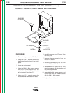
REPLACEMENT PROCEDURE
1. Install plug J10 into the new display
board.
2. Mount the display board onto the six
mounting pins.
3. Install plug J11 into the new display
board.
4. Reinstall the control panel.
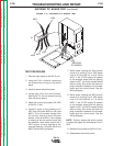
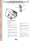
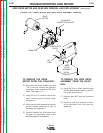
REMOVAL PROCEDURE
1. Remove input power to the DH-10 unit.
2. Using the 5/16 in. nutdriver, remove the
two screws from the top of the control
panel.
3. Lower the control panel.
4. Locate and remove plug J11 from the
display board. Observe static electricity
precautions. See Figure F.6.
5. Carefully pry the display board from the
six mounting pins. Note that the keypad
is still attached to the display board via
plug J10.
6. Carefully remove plug J10 from the dis-
play board.
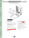
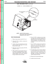
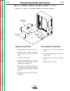
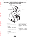
FIGURE F.6 — DISPLAY PC BOARD REMOVAL AND REPLACEMENT.
DISPLAY PC BOARD REMOVAL AND REPLACEMENT
(continued)
MOUNTING
PIN
DISPLAY
PC BOARD
J11
J10