


Return to Section TOC Return to Section TOC Return to Section TOC Return to Section TOC
Return to Master TOC Return to Master TOC Return to Master TOC Return to Master TOC
B-9
OPERATION
B-9
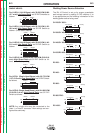
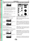
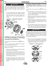
Check to be sure the Retaining Spring has fully
returned to the locking position and has SECURELY
locked the Readi-Reel Cage in place. Retaining
Spring must rest on the cage, not the welding elec-
trode.
___________________________________________
9. To remove Readi-Reel from Adapter, depress
retaining spring tab with thumb while pulling the
Readi-Reel cage from the molded adapter with
both hands. Do not remove adapter from
spindle.
FIGURE B.1 — READI-REEL MOUNTING.
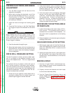
To Mount 10 to 44 lb (4.5 to 20 kg) Spools
(12 in/300 mm Diameter) or 14 lb (6 kg)
Innershield Coils (FIGURE B.1):
The Spindle should be located in the LOWER mount-
ing hole.
(For 8 in. (200 mm) spools, a K468 spindle adapter
must first be slipped onto spindle.)
(For 13-14 lb. (6 kg) Innershield coils, a K435 Coil
Adapter must be used).
1. Depress the Release Bar on the Retaining Collar
and remove it from the spindle.
2. Place the spool on the spindle making certain the
spindle brake pin enters one of the holes in the
back side of the spool. Be certain the wire
comes off the reel in a direction so as to de-reel
from the bottom of the coil.
3. Re-install the Retaining Collar. Make sure that
the Release Bar “pops up” and that the collar
retainers fully engage the retaining groove on the
spindle.
DH-10
CAUTION
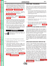
To Mount a 50 to 60 lb (22.7 to 27.2 kg)
Coil: (Using K1504-1 Coil Reel) (For 50 to 60
lb Readi-Reels a K438 Readi-Reel Adapter must be
used).
The Spindle must be located in the UPPER mounting
hole.
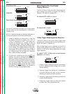
1. With the K1504-1 Coil Reel mounted on to the
2 in. (51 mm) spindle (or with reel laying flat on
the floor) loosen the spinner nut and remove the
reel cover. (See Figure B.2).
2. Before cutting the tie wires, place the coil of elec-
trode on the reel so it unwinds from the bottom as
the reel rotates.
3. Tighten the spinner nut against the reel cover as
much as possible by hand using the reel cover
spokes for leverage. DO NOT hammer on the
spinner nut arms.
4. Cut and remove only the tie wire holding the free
end of the coil. Hook the free end around the rim
of the reel cover and secure it by wrapping it
around. Cut and remove the remaining tie wires.
Always be sure the free end of the coil is securely
held while the tie wires are being cut and until the wire
is feeding through the drive rolls. Failure to do this will
result in “backlashing” of the coil, which may tangle
the wire. A tangled coil will not feed so it must either
be untangled or discarded.
___________________________________________
5. Be sure the coil reel is engaged with the spindle
brake pin and the Release Bar on the Retaining
Collar “pops up” and that the collar retainers fully
engage the retaining groove on the spindle.
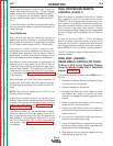
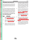
FIGURE B.2 — KI504-1 COIL REEL.
CAUTION
SPINNER NUT
COVER
PLATE
SLOTS
CARDBOARD
COIL LINER
COIL
TIE WIRE
SPRING
LOADED ARM
REEL