


Return to Section TOC Return to Section TOC Return to Section TOC Return to Section TOC
Return to Master TOC Return to Master TOC Return to Master TOC Return to Master TOC
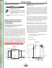
Single Drive 4-Roll Kits (KP655 and KP656)
1. Turn OFF welding power source.
2. Release both quick release levers by sliding the
levers sideways into the open positions.
3. Remove clamping screw & clamping collar from
the drive shaft closest to the incoming side of the
feeder.
4. Install drive roll onto keyed shaft. (Do not exceed
the maximum wire size rating of the wire drive.)
Replace collar and tighten clamping screw.
5. Back out the set screw for the middle guide tube.
Install the middle guide tube and slide it up
against the drive roll. DO NOT TIGHTEN THE
MIDDLE GUIDE AT THIS TIME.
6. Install the outgoing drive roll following the same
procedure as steps 3 & 4.
7. Center the middle guide between the two drive
rolls and tighten in place.
8. Back out the screws for the incoming and outgo-
ing guide tubes.
9. Install the longer guide tube in the rear hole near
the incoming drive roll. Slide the tube in until it
almost touches the roll. Tighten in place.
10. Install the remaining guide tube in the front hole.
Be certain that the proper plastic insert is used.
Fine wire chisel point tube must have largest
radius next to drive roll. Tighten in place.
11. Re-latch both quick release levers.
12. To start new electrode, straighten the first 6 in.
(150 mm) and cut off the first 1 in. (25 mm).
Insert free end through the incoming tube. Press
gun trigger and push wire into the drive roll.
To set idle pressure, see
Idle Roll Pressure Setting
in
Operation
.
DH Drive Roll Kit Installation
(KP1505 and KP1507)
1. Turn OFF Welding Power Source.
2. Pull open Pressure Door to expose rolls and wire
guides.
3. Remove Outer Wire Guide by turning knurled
thumb screws to unscrew from Feedplate.
4. Remove drive rolls, if any are installed, by pulling
straight off shaft. Remove inner guide.
A-7
INSTALLATION
DH-10
A-7
5. Insert inner Wire Guide, groove side out, over the
two locating pins in the feedplate.
6. Install each drive roll by pushing over shaft until it
butts up against locating shoulder on the drive
roll shaft. (Do Not exceed maximum wire size
rating of the wire drive).
7. Install Outer Wire Guide by sliding over locating
pins and tightening in place.
8. Engage upper drive rolls if they are in the “open”
position and close Pressure Door.
To set idle roll pressure, see
Idle Roll Pressure
Setting
in
Operation
.
GUN AND CABLE ASSEMBLIES
WITH STANDARD CONNECTION
The DH Wire Drive Heads each require a K1500 Gun
Adapter installed See
Gun Adapters
in
Accessories
section.
GMAW Guns
An expanding line of Magnum gun and cable assem-
blies are available to allow welding with solid and
cored electrodes using the GMAW process. See the
appropriate Magnum literature for descriptions of the
200 to 550 ampere air cooled gun and cables that are
available. Gun cable lengths range from 10 ft (3.0 m)
to 25 ft (7.6 m) and feed electrode sizes 0.025 in.
(0.6 mm) to 3/32 in. (2.4 mm). The entire line of
Magnum Fast-Mate gun and cable assemblies can
also be used by installing a K489-2 Fast-Mate adapter
kit. See
Gun and Cable Assemblies with Fast-Mate
Connection
in this section for details.
Innershield Guns
K126 and K115 gun and cable assemblies are avail-
able to allow welding with Innershield electrodes. Gun
cable lengths range from 10 ft (3.0 m) to 15 ft (4.5 m)
The 350 ampere K126 will feed electrode sizes
0.062 in. (1.6 mm) to 3/32 in. (2.4 mm). The 450
ampere K115 will feed 5/64 in. (2.0 mm) to 3/32 in.
(2.4 mm) electrode.
Three smoke extraction gun and cable assemblies are
available, 250 ampere K309, 350 ampere K206 and
the 500 ampere K289. All gun cable lengths are 15 ft
(4.5 m). These guns will feed electrode sizes 0.062 in.
(1.6 mm) to 3/32 in. (2.4 mm) and require the use of
the K184 vacuum unit for use with the DH-10.