


F-20
TROUBLESHOOTING AND REPAIR
F-20
DH-10
the control board or associated leads or
plugs may be faulty. See the Wiring
Diagram.
6. Activate the gun trigger. Make sure the
motor is running. Check for the pres-
ence of approximately 5.0 VDC from
blue lead #555 (+) to black lead #500
(-). The 5.0 VDC represents the correct
feedback voltage from the hall effect
device to the control board.
7. If the above voltage reading is not cor-
rect, the hall effect device may need to
be adjusted or replaced. See
Tach
Adjustment Procedure
.
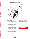
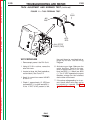
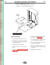
TEST PROCEDURE
1. Remove input power to the DH-10 unit.
2. Using the 5/16 in. nutdriver, remove the
wire drive cover.
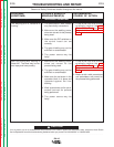
3. Locate the three hall effect leads (blue,
red and black). See Figure F.2.
4. Apply the correct input power (42 VAC)
to the DH-10.
5. Check for approximately 12 VDC from
red lead #512 (+) to black lead #500 (-).
If the 12 VDC is NOT present or low,
FIGURE F.2 — TACH FEEDBACK TEST.
LINCOLN
ELECTRIC
LINCOLN
ELECTRIC
HALL EFFECT
DEVICE (TACH)
#500
BLACK
#512
RED
#555
BLUE
TACH ADJUSTMENT AND FEEDBACK TEST
(continued)
Return to Section TOC Return to Section TOC Return to Section TOC Return to Section TOC
Return to Master TOC Return to Master TOC Return to Master TOC Return to Master TOC