


Return to Section TOC Return to Section TOC Return to Section TOC Return to Section TOC
Return to Master TOC Return to Master TOC Return to Master TOC Return to Master TOC
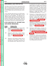
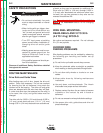
SAFETY PRECAUTIONS
Observe all additional Safety Guidelines detailed
throughout this manual.
D-2
MAINTENANCE
D-2
DH-10
of teeth so they can be reversed for additional life.
Drive rolls for 0.023 in. (0.6 mm) through 0.052 in.
(1.3 mm) solid electrodes and aluminum sizes have
no teeth, but use two grooves so they also can be
reversed for additional life.
See
Procedure to Install Drive Roll and Guide
Tubes
in the
Installation
section for roll changing
instructions.
WIRE REEL MOUNTING -
READI-REELS AND 10 TO 30 lb
(4.5 TO 14 kg) SPOOLS
No routine maintenance required. Do not lubricate
2 in. (51 mm) spindle.
AVOIDING WIRE
FEEDING PROBLEMS
Wire feeding problems can be avoided by observing
the following gun handling and feeder set up
procedures:
a) Do not kink or pull cable around sharp corners.
b) Keep the electrode cable as straight as possible
when welding or loading electrode through cable.
c) Do not allow dolly wheels or trucks to run over
cables.
d) Keep cable clean by following maintenance
instructions.
e) Use only clean, rust-free electrode. The Lincoln
electrodes have proper surface lubrication.
f) Replace contact tip when the arc starts to become
unstable or the contact tip end is fused or
deformed.
g) Do not use excessive wire spindle brake settings.
h) Use proper drive rolls, guide tubes and drive roll
pressure settings.
ROUTINE MAINTENANCE
Drive Rolls and Guide Tubes
After feeding every coil of wire, inspect the drive roll
section. Clean it as necessary. Do not use a solvent
for cleaning the idle roll because it may wash the
lubricant out of the bearing. The driver roll and guide
tubes are stamped with the wire sizes they will feed.
If a wire size other than that stamped on the roll(s) is
to be used, the roll(s) and guide tubes must be
changed.
The drive rolls for 0.035 in. (0.9 mm) through 0.052 in.
(1.3 mm) cored electrode and 1/16 in. (1.6 mm)
through 3/32 in. (2.4 mm) electrode have a double set
WARNING
ELECTRIC SHOCK can kill.
• Do not touch electrically live parts
such as output terminals or internal
wiring.
• When inching with gun trigger, elec-
trode and drive mechanism are
“hot” to work and ground and could
remain energized several seconds
after the gun trigger is released.
• Turn OFF input power at welding
power source before installation or
changing drive roll and/or guide
tubes.
• Welding power source must be con-
nected to system ground per the
National Electrical Code or any
applicable local codes.
• Only qualified personnel should per-
form this installation.