


Return to Section TOC Return to Section TOC Return to Section TOC Return to Section TOC
Return to Master TOC Return to Master TOC Return to Master TOC Return to Master TOC
F-40
TROUBLESHOOTING AND REPAIR
F-40
DH-10
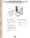
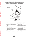
8. Place the entire assembly into the
DH-10 unit. Align the mounting holes
with wire feeder base.
9. Secure the assembly to the wire feeder
base using the four screws, lock wash-
ers and flat washers previously
removed.
10. Connect the gas hose to the brass gun
conductor block.
11. Connect the motor armature leads.
12. Connect the tach (hall effect device)
leads.
13. Connect lead #67 quick connects
together.
14. Connect the electrode cable to the to
the wire feed assembly.
15. Replace any cut or removed cable ties.
16. Install the wire drive cover.
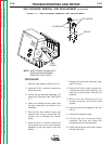
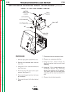
REPLACEMENT PROCEDURES
1. Carefully slide the wire drive assembly
and gear box together.
2. Tighten the two Allen type screws at
the bottom of the wire drive unit using
the 3/16 in. Allen wrench.
3. Attach lead #67 to the conductor block.
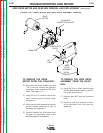
4. Carefully slide the drive motor into the
gear box assembly. Be sure to position
the motor leads so that they can be
properly connected.
5. Install the slot head screws that mount
the “top” of the drive motor to the gear
box.
6. Install the mounting screw located
inside the gear box using the 5/16 in.
wrench.
7. Install the gear box inspection cover
and secure it with the slot head screws
and nut previously removed.
WIRE DRIVE MOTOR AND GEAR BOX REMOVAL AND REPLACEMENT
(continued)