


Return to Section TOC Return to Section TOC Return to Section TOC Return to Section TOC
Return to Master TOC Return to Master TOC Return to Master TOC Return to Master TOC
A-9
INSTALLATION
DH-10
A-9
GMAW Shielding Gas
The customer must provide a cylinder of shielding
gas, a pressure regulator, a flow control valve, and a
hose from the flow valve to the gas inlet fitting of the
wire drive unit.
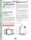
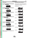
Connect a supply hose from the gas cylinder flow
valve outlet to the 5/8-18 female inert gas fitting on the
back panel of the wire drive or, if used, on the inlet of
the Gas Guard regulator. (See Below).
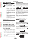
Gas Guard Regulator - The Gas Guard Regulator is
an optional accessory (K659-1) on these models.
Install the 5/8-18 male outlet of the regulator to the
5/8-18 female gas inlet on the back panel of the wire
drive. Secure fitting with flow adjuster key at top.
Attach gas supply to 5/8-18 female inlet of regulator
per instructions above.
CYLINDER may explode if damaged.
• Keep cylinder upright and chained to
support.
• Keep cylinder away from areas where it may be
damaged.
• Never lift welder with cylinder attached.
• Never allow welding electrode to touch cylinder.
• Keep cylinder away from welding or other live electri-
cal circuits.
BUILDUP OF SHIELDING GAS may
harm health or kill.
• Shut off shielding gas supply when not
in use.
SEE AMERICAN NATIONAL STANDARD Z-49.1,
“SAFETY IN WELDING AND CUTTING” PUB-
LISHED BY THE AMERICAN WELDING SOCIETY.
------------------------------------------------------------------------
WARNING
ELECTRICAL INSTALLATION
Input Cable: DH-10 Control to Power
Source
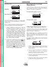
Available Cable Assemblies:
K1501 (Control Cable Only) Consists of a 9-conductor
control cable with a 14-pin control cable plug,
without electrode cable, and is available in lengths of
10 ft (3 m), 17 ft (5 m), 25 ft (7.6 m), 33 ft (10 m), 50 ft
(15 m) and 100 ft (30 m).
K1502 Consists of a 9-conductor control cable with a
14-pin plug and a 3/0 (85 mm
2
) electrode cable with
stud terminal. It is rated at 600 amps, 60% duty cycle
and is available in lengths of 10 ft (3 mm), 17 ft (5 m),
25 ft (7.6 m), 33 ft (10 m) and 50 ft (15 m) and 100 ft
(30 m) is also available with a 4/0 (107 mm
2
) elec-
trode cable.
ELECTRIC SHOCK can kill.
• Do not touch electrically live parts
such as output terminals or internal
wiring.
• When inching with gun trigger, elec-
trode and drive mechanism are
“hot” to work and ground and could
remain energized several seconds
after the gun trigger is released.
• Turn OFF input power at welding
power source before installation or
changing drive roll and/or guide
tubes.
• Welding power source must be con-
nected to system ground per the
National Electrical Code or any
applicable local codes.
• Only qualified personnel should per-
form this installation.
WARNING
Observe all additional Safety Guidelines detailed
throughout this manual.