


F-18
TROUBLESHOOTING AND REPAIR
F-18
DH-10
5. If the correct voltages are NOT present
at the armature motor leads, check the
associated leads and plugs for loose or
faulty connections. See the Wiring
Diagram. If the leads and connections
are OK, the control board may be
faulty.
6. If the correct voltages are present at
the motor armature leads and the motor
does not run and vary speed with
changes in armature voltage, the motor
or gear box may be faulty. See
Wire
Drive Motor
and
Gear Box Removal
and Replacement
.
7. Install the wire drive cover.
TEST PROCEDURE
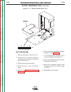
1. Remove input power to the DH-10 unit.
2. Using the 5/16 in. nutdriver, remove the
wire drive cover.
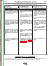
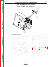
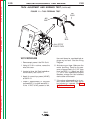
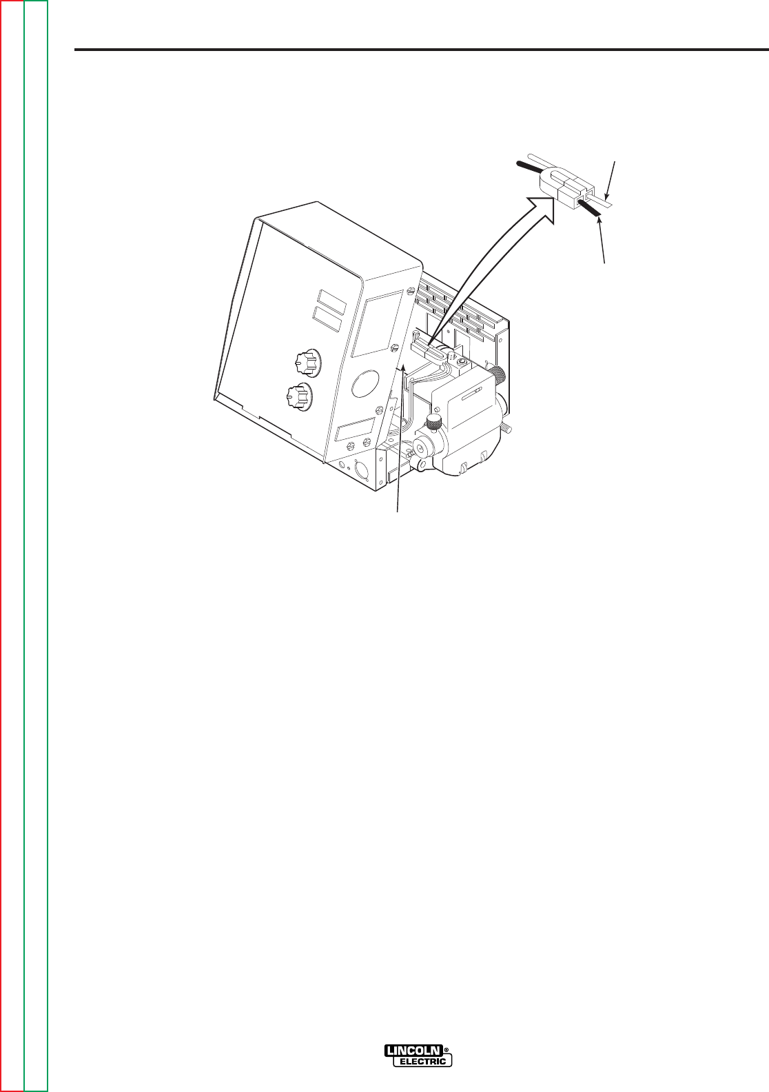
3. Locate the motor armature leads for the
motor to be tested (one black (-) lead
and one white (+) lead). Do not discon-
nect the leads. See Figure F.1.
4. Apply the correct input power (42 VAC)
to the DH-10. Activate the gun trigger.
With the motor running, check the
armature voltage at the black (-) and
white (+) leads. The normal voltage
range is approximately 1 to 25 VDC
depending on motor speed. When the
armature voltage is increased the motor
speed should also increase.
FIGURE F.1 — WIRE DRIVE MOTOR TEST.
(+)WHITE
LEAD
(-)BLACK
LEAD
LINCOLN
ELECTRIC
DRIVE
MOTOR
LINCOLN
ELECTRIC
WIRE DRIVE MOTOR TEST
(continued)
Return to Section TOC Return to Section TOC Return to Section TOC Return to Section TOC
Return to Master TOC Return to Master TOC Return to Master TOC Return to Master TOC
Return to Section TOC Return to Section TOC Return to Section TOC Return to Section TOC
Return to Master TOC Return to Master TOC Return to Master TOC Return to Master TOC