


Return to Section TOC Return to Section TOC Return to Section TOC Return to Section TOC
Return to Master TOC Return to Master TOC Return to Master TOC Return to Master TOC
F-21
TROUBLESHOOTING AND REPAIR
F-21
DH-10
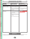
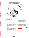
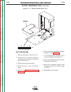
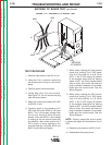
3. Using the 9/16 in. wrench loosen the
locking nut.
4. Gently screw the hall effect module into
the mounting plate until it just touches
and stops against the rotating part
inside the gearbox. See Figure F.2.
5. Back the module out 1/2 turn. Using the
9/16 in. wrench and carefully snug the
locknut without rotating the module
position.
6. Install the wire drive cover.
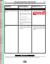
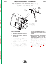
TACH ADJUSTMENT
PROCEDURE
Proper positioning of the module is critical
to the proper operation the DH-10 wire
feeder. If the device is not screwed in far
enough the motor speed could be unstable
or run at full speed with no control. If
screwed in too far it will rub a moving part
inside the gearbox.
1. Remove input power to the DH-10 wire
feeder.
2. Make sure the module is securely
attached to the gearbox.
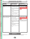
TACH ADJUSTMENT AND FEEDBACK TEST
(continued)