


Return to Section TOC Return to Section TOC Return to Section TOC Return to Section TOC
Return to Master TOC Return to Master TOC Return to Master TOC Return to Master TOC
F-30
TROUBLESHOOTING AND REPAIR
F-30
DH-10
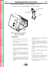
6. If the 10 VDC is missing or low, check
the leads and connections between the
solenoid and the control board. See the
Wiring Diagram. If the leads and con-
nections are OK the control board may
be faulty.
7. If the 10 VDC is present at the solenoid
leads and the solenoid does not
activate the solenoid may be faulty.
Normal solenoid coil resistance is
approximately 22 ohms.
8. The solenoid(s) can be further checked
by disconnecting the solenoid leads
from the DH-10 wiring harness and
applying an external 12 VDC supply to
the leads. If the solenoid does not acti-
vate the solenoid is faulty.
9. Reconnect all disconnected leads.
10. Install the wire drive cover.
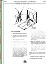
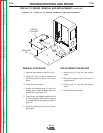
TEST PROCEDURE
1. Remove input power to the DH-10 unit.
2. Using the 5/16 in. nutdriver, remove the
wire drive cover.
3. Locate the gas solenoids and lead
quick connects. See Figure F.5. Do not
disconnect the leads.
4. Apply the correct input power (42 VAC)
to the DH-10 unit.
5. While pressing the gas purge button or
activating the appropriate gun trigger,
check for approximately 10 VDC at the
solenoid leads. If the 10 VDC is present
the gas solenoid should activate.
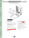
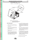
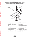
FIGURE F.5 — GAS SOLENOID TEST.
GAS SOLENOID TEST
(continued)
GAS SOLENOID
LEADS
NOTE: WIRE FEEDER SHOWN
WITH DRIVE MOTOR ASSEMBLY
REMOVED FOR CLARITY
GAS
SOLENOID