


Return to Section TOC Return to Section TOC Return to Section TOC Return to Section TOC
Return to Master TOC Return to Master TOC Return to Master TOC Return to Master TOC
A-6
INSTALLATION
DH-10
A-6
To remove feedplate:
a. Loosen the clamping collar screw using a
3/16 in. Allen wrench. The clamping collar
screw is accessed from the bottom of the
feedplate. It is the screw which is perpen-
dicular to the feeding direction.
b. Loosen the retaining screw, which is also
accessed from bottom of feeder, using a
3/16 in. Allen wrench. Continue to loosen
the screw until the feedplate can be easily
pulled off of the wire feeder.
3. Loosen, but do not remove, the screw on the
lower right face of the feedplate with a 3/16 in.
Allen wrench.
4. Remove the screw on the left face of the feed-
plate. If changing from high speed (larger gear)
to low speed (smaller gear), line the lower hole
on the left face of the feedplate with the threads
on the clamping collar. Line the upper hole with
the threads to install larger gear for high speed
feeder. If feedplate does not rotate to allow holes
to line up, further loosen the screw on right face
of feedplate.
5. Install gear onto output shaft and secure with flat
washer, lock washer, and Phillips head screw
which were previously removed.
6. Tighten the screw on lower right face of feed-
plate.
7. Install gear onto output shaft and secure with flat
washer, lock washer, and Phillips head screw
which were previously removed.
8. Re-attach feedplate to wire feeder if removed in
Step 2.
9. Feedplate will be rotated out-of-position due to
the gear change. To re-adjust angle of feedplate:
a. Loosen the clamping collar using a 3/16 in.
Allen wrench. The clamping collar screw is
accessed from the bottom of the feedplate.
It is the screw which is perpendicular to the
feeding direction.
b. Rotate feedplate to the desired angle and
tighten clamping collar screw.
10. Make sure to properly set the switch (S2) code
on the control board inside the control box for
the new gear size installed. See
Operation,
Setting the DIP Switches
for setting
instructions.
WIRE FEED DRIVE ROLL KITS
NOTE: The maximum rated solid and cored wire
sizes for each wire drive head and selected drive ratio
is shown on the
Specifications
in the front of this
section.
The electrode sizes that can be fed with each roll and
guide tube are stenciled on each part. Check the kit
for proper components.
Single Head Drives (K679) use 4-Roll drive roll kits
with 2 driven rolls, per
Table C.1
in
Accessories
.
These kits are common with those used for the 4-Roll
LN-7 GMA and LN-9 GMA Lincoln Wire Feeders, but
are not common with those used with the DH wire
drive units. Installation instructions are included with
the kits.
DH Double Head Drives use 4-Roll drive roll kits with
4 driven rolls, per
Table C1
in
Accessories
. Each
head requires a separate drive roll kit.
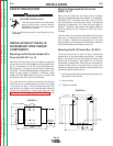
PROCEDURE TO INSTALL DRIVE
ROLL AND WIRE GUIDES
WARNING
ELECTRIC SHOCK can kill.
• Do not touch electrically live parts
such as output terminals or internal
wiring.
• When inching with gun trigger, elec-
trode and drive mechanism are
“hot” to work and ground and could
remain energized several seconds
after the gun trigger is released.
• Turn OFF input power at welding
power source before installation or
changing drive roll and/or guide
tubes.
• Welding power source must be con-
nected to system ground per the
National Electrical Code or any
applicable local codes.
• Only qualified personnel should per-
form this installation.
Observe all additional Safety Guidelines detailed
throughout this manual.