


Return to Section TOC Return to Section TOC Return to Section TOC Return to Section TOC
Return to Master TOC Return to Master TOC Return to Master TOC Return to Master TOC
TROUBLESHOOTING & REPAIR
F-57 F-57
RANGER 9 RANGER 9
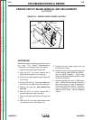
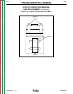
OUTPUT RECTIFIER BRIDGE REMOVAL
AND REPLACEMENT (continued)
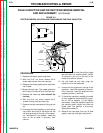
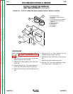
12. With the 3/8” wrench and slot head screw
driver, remove the four mounting screws
(two on each side). Note the placement of
the nylon insulators. These must be in
place when you reinstall the rectifier
bridge assembly in order to electrically
insulate the bridge from the choke lam-
ination assembly.
13. Remove the rectifier assembly by tilting it
up and lifting it toward the front of the
machine.
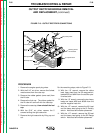
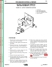
14. Reassembly: Refer to the Wiring Diagram
for proper connections to the positive and
negative sides of the rectifier assembly.
The two sides of the bridge are marked +
and -, respectively.
NOTE: Use Dow Corning 340 on all aluminum
electrical connection surfaces.
15. WIth the 3/8” wrench and slot head screw
driver, install the four mounting screws
(two on each side). Note the placement of
the nylon insulators. These must be in
place when you install the rectifier
bridge assembly in order to electrically
insulate the bridge from the choke lam-
ination assembly.
16. With the 1/2” wrench, install the S2 lead
and the heavy lead going to the Range
switch. Note the order of fasteners and
leads.
17. With the 1/2” wrench, install the W1 lead
and the heavy lead going to the Polarity
switch. Note the order of fasteners and
leads.
18. With the 1/2” wrench, install the two heavy
leads and leads #236 and #236A to the
rectifier negative heat sink. Note the order
of fasteners: bolt and flat washer from the
bottom up through the heat sink; on top,
leads, flat washer, lock washer, and nut.
19. With the 1/2” wrench, install the choke
lead, the heavy lead, and leads #235 and
#242 to the rectifier positive heat sink.
Note the order of fasteners: bolt and flat
washer from the bottom up through the
heat sink; on top, leads, flat washer, lock
washer, and nut.
20. Reinstall the case side, fuel cap, lift bale
gasket, case top, and spark plug wire.