


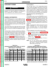

AUXILIARY POWER
Be sure that any electrical equipment plugged into the
generator AC power receptacles can withstand a
±10% voltage and a ±3% frequency variation.
GENERAL INFORMATION
The RANGER 9 generator is rated at 9000 continuous
watts. It provides both 115 volt and 230 volt power.
You can draw up to 80 amps total from the 115 volt
receptacles, but no more than 20 amps (15 amps CSA)
from each receptacle at once. See Tables B.4A and
B.4B. Up to 40 amps can be drawn from the single 230
volt receptacle.
The current rating of any plug used must be at least
equal to the current load being drawn from the recep-
tacle. Do not try to connect the receptacles in paral-
lel.
Electrical loads in watts are calculated by multiplying
the voltage rating of the load by the number of amps it
draws. (This information is given on the load device
nameplate.) For example, a device rated 115 volts, 2
amps will need 230 watts of power (115 x 2 = 230).
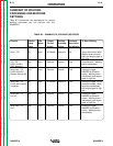
You can use Table B.6, GENERATOR POWER APPLI-
CATIONS, to determine the wattage requirements of
some common types of loads you can power with the
RANGER 9. Be sure to read the notes at the bottom
of the table.
Powering Motors
You can start most 1.5 HP, single-phase electric
motors if there is no load on the motor or other load
connected to the RANGER 9. After starting, the motor
may be run at full load. Larger motors (up to 2 HP)
may be started and run as long as you don’t exceed
the current rating of the receptacle. This may mean
that only 230 volt motors of this size may be operated.
Using Auxiliary Power and Welding at the
Same Time
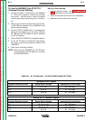
It is possible to weld and use the RANGER 9 for auxil-
iary power at the same time. However, the size of the
loads you can power is reduced when you weld. See
Table B.5 in this section of the manual for a list of per-
missible simultaneous welding and load ratings. The
table assumes that power is being drawn from either a
115 volt or the 230 volt receptacle, but not both at the
same time.
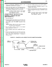
NOTE: For simultaneous welding and power, set the
OUTPUT CONTROL at “10” for maximum auxiliary
power. At settings below “10,” only incandescent
loads should be connected to the auxiliary recepta-
cles.
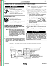
To use the generator as an auxiliary power supply:
1. Start the gasoline engine. See ENGINE OPERA-
TION in this section of the manual.
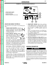
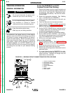
2. Set the IDLER CONTROL to the desired operating
mode, HIGH or AUTO. Set the OUTPUT CON-
TROL to “10.” See Figure B.1.
3. Plug the load(s) into the appropriate 115 volt or
230 volt power receptacle.
NOTE: The 115 volt auxillary power receptacles
should only be used with three-wire grounded
type plugs or approved double insulated
devices with two-wire plugs.
OPERATION
B-14 B-14
RANGER 9 RANGER 9
Return to Section TOC Return to Section TOC Return to Section TOC Return to Section TOC
Return to Master TOC Return to Master TOC Return to Master TOC Return to Master TOC
WARNING
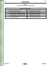
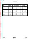
TABLE B.4A
MAXIMUM CURRENT DRAW FROM 115V DUPLEX
RECEPTACLES – NO WELDING
K1420-1 K1420-2 (CSA)
Load From Each Total Each Total
115V/230V Half of from Half of from
Dual Voltage Each 115V Both 115V Each 115V Both 115V
Receptacle Duplex Duplexes Duplex Duplexes
0 20* 78 15 60
2.2 KW 20* 60 15 60
4.5 KW 20* 40 15 40
6.7 KW 20* 20 15 20
9.0 KW 0 0 0 0
*NEMA 5-20P plug required for 20 amp draw.
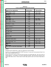
TABLE B.4B
MAXIMUM CURRENT DRAW FROM OPTIONAL
115V GFCI DUPLEX RECEPTACLES – NO WELDING
K1420-1* K1420-2**
Load From Each Total Each Total
115V/230V Half of from Half of from
Dual Voltage Each 115V Both 115V Each 115V Both 115V
Receptacle Duplex Duplexes Duplex Duplexes
015401530
2.2 KW 15 40 15 30
4.5 KW 15 40 15 30
6.7 KW 15 20 15 20
9.0 KW 0 0 0 0
*Maximum current draw from each 115V GFCI Duplex is 20 amps.
**Maximum current draw from each 115V GFCI Duplex is 15 amps.