


Return to Section TOC Return to Section TOC Return to Section TOC Return to Section TOC
Return to Master TOC Return to Master TOC Return to Master TOC Return to Master TOC
TROUBLESHOOTING & REPAIR
F-10 F-10
RANGER 9 RANGER 9
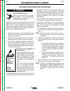
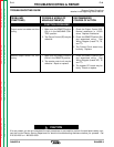
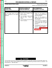
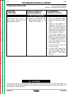
Observe Safety Guidelines TROUBLESHOOTING GUIDE
detailed in the beginning of this manual.
CAUTION
If for any reason you do not understand the test procedures or are unable to perform the test/repairs safely, con-
tact the Lincoln Electric Service Department for electrical troubleshooting assistance before you proceed. Call
216-383-2531 or 1-800-833-9353.
PROBLEMS
(SYMPTOMS)
POSSIBLE AREAS OF
MISADJUSTMENT(S)
RECOMMENDED
COURSE OF ACTION
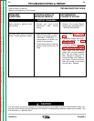
ENGINE PROBLEMS
Engine will not idle down to low
speed. Machine has normal weld
output and auxiliary power.
1. Make sure the Idler switch (S5)
is in the “Auto” position.
2. Make sure there is NOT an
external load on the weld termi-
nals nor the auxiliary power
receptacles.
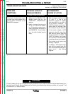
1. With the Idler switch (S5) in the
“AUTO” position and the engine
running, check for the presence
of 12VDC at leads #224D to
#214, located at the Idler sole-
noid. If 12VDC is present and
the idler solenoid is not activat-
ing, then the solenoid may be
faulty or there is a mechanical
restriction preventing it from
functioning.
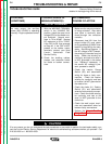
2. If there is NOT 12VDC at leads
#224D to #214, then test for
12VDC from lead #224D to
ground (lead #5). See Wiring
Diagram. If 12VDC is present,
then check lead #214 for conti-
nuity (zero ohms) from the idler
solenoid to the printed circuit
board plug 8J1. Also check the
idler switch (S5) and the associ-
ated leads. See Wiring
Diagram. If the above are OK,
then the printed circuit board
may be faulty. Replace.
3. If there is NOT 12VDC from lead
#224D to ground (lead #5), then
check the wiring to the engine
terminal block connection. See
Wiring Diagram.