


Return to Section TOC Return to Section TOC Return to Section TOC Return to Section TOC
Return to Master TOC Return to Master TOC Return to Master TOC Return to Master TOC
TROUBLESHOOTING & REPAIR
F-60 F-60
RANGER 9 RANGER 9
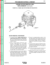
OUTPUT CAPACITOR REMOVAL
AND REPLACEMENT (continued)
Be sure to follow the recommended static-free
methods for handling printed circuit boards.
Failure to do so can result in permanent damage
to the equipment.
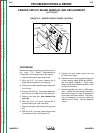
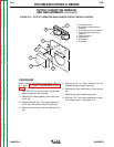
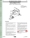
9. With the 1/4” nut driver, remove the five
screws holding the printed circuit board.
10. Carefully pull the printed circuit board aside,
supported by the leads still connected to it,
so that all the screws that mount the capac-
itor bank to the vertical baffle are accessi-
ble.
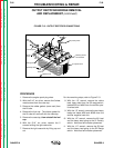
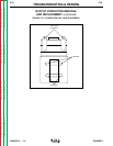
11. With the volt/ohmmeter, check the voltage
across each of the four output capacitors. If
a voltage is present, use a 25-watt resistor
to discharge each capacitor.
12. With the 1/2” wrench, remove the two nuts,
bolts, and associated washers holding the
two heavy leads to the positive and negative
capacitor buss bars.
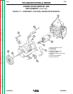
13. With the phillips head screw driver, remove
the four mounting screws holding the
capacitor bank assembly to the vertical baf-
fle.
14. Carefully remove the capacitor bank assem-
bly.
15. To replace the capacitor bank assembly,
mount the assembly to the vertical baffle
with four phillips head screws.
16. With the 1/2” wrench, attach the two heavy
leads and associated fasteners to the posi-
tive and negative buss bars. Observe
capacitor polarity.
17. With the 1/4” nut driver, mount the printed
circuit board to the vertical baffle (five
screws).
18. With the 5/16” nut driver, install the printed
circuit board cover.
19. Reinstall the case side, fuel cap, lift bail gas-
ket, and case top.
CAUTION