


• Quiet engine muffler with reversible exhaust feature
for right or left side.
• All copper alternator windings and high quality insu-
lation for dependable long life.
• Automatic engine shutdown protection for low oil
pressure.
• Automatic engine idler goes to low idle 10 to 14
seconds after welding for greater fuel economy;
includes high idle switch.
• Standard Remote Control Receptacle provides
interface for Lincoln remote control accessories.
Both 6 pin and 14 pin amphenols are provided for
ease in hooking up wire feeders.
• Canadian Standard Association (CSA) approved
models available; include integrated generator out-
put overload protection through two 50 amp circuit
breakers.
WELDING CAPABILITY
The RANGER 9 is rated 250 amps, 25 volts constant
current AC or 250 amps, 25 volts constant current DC
(250 amps 25 volts constant voltage DC) at 100% duty
cycle on a ten-minute basis.
The current is continuously variable from 40 to 250
amps AC or 40 to 250 amps DC. The RANGER 9 can
weld with all 3/32 and most 1/8 inch and 1/16 diame-
ter Lincoln AC stick electrodes. Wire feed processes
using wire diameters from .030 to .068 inch are possi-
ble, depending on the specific process and wire feed-
er. (See LIMITATIONS.)
LIMITATIONS
• The RANGER 9 is not recommended for any
processes besides those that are normally per-
formed using stick welding (SMAW), TIG welding,
MIG (GMAW) welding and Innershield
®
(FCAW)
welding. Specific limitations on using the
RANGER 9 for these processes are described in the
WELDING OPERATION section of this manual.
• The RANGER 9 is not recommended for pipe thaw-
ing.
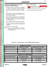
• During welding, generator power is limited and out-
put voltages can drop. Therefore, DO NOT OPER-
ATE ANY SENSITIVE ELECTRICAL EQUIPMENT
WHILE YOU ARE WELDING. See Table B.4 for per-
missible simultaneous welding and auxiliary power
loads.
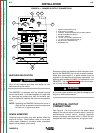
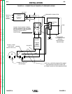
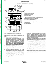
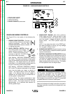
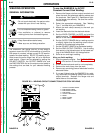
CONTROLS AND SETTINGS
All generator/welder controls are located on the
Output Control Panel of the machine case front.
Gasoline engine choke control, idler control, and
start/stop controls are also on the case front. See
Figure B.1 and the explanations that follow.
OPERATION
B-4 B-4
RANGER 9 RANGER 9
Return to Section TOC Return to Section TOC Return to Section TOC Return to Section TOC
Return to Master TOC Return to Master TOC Return to Master TOC Return to Master TOC