


Return to Section TOC Return to Section TOC Return to Section TOC Return to Section TOC
Return to Master TOC Return to Master TOC Return to Master TOC Return to Master TOC
TROUBLESHOOTING & REPAIR
F-11 F-11
RANGER 9 RANGER 9
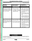
TROUBLESHOOTING GUIDE Observe Safety Guidelines
detailed in the beginning of this manual.
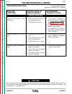
CAUTION
If for any reason you do not understand the test procedures or are unable to perform the test/repairs safely, con-
tact the Lincoln Electric Service Department for electrical troubleshooting assistance before you proceed. Call
216-383-2531 or 1-800-833-9353.
PROBLEMS
(SYMPTOMS)
POSSIBLE AREAS OF
MISADJUSTMENT(S)
RECOMMENDED
COURSE OF ACTION
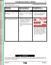
ENGINE PROBLEMS
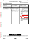
Engine will not go to high idle when
attempting to weld. Welding out-
put is normal when Idler switch is
in “HIGH” position. Automatic idle
function works properly when the
auxiliary power is loaded.
1. Make sure the welding cables
and connections are tight.
2. If attempting to “scratch” start,
the WELDING TERMINALS
switch (S6) must be in the
“ALWAYS ON” position.
1. Check for broken or faulty con-
nections in the sensing leads
(#254 and #254A). Make sure
their connections are tight at
the work output terminal and
also at the Polarity switch. See
Wiring Diagram.
2. Make sure the leads are looped
three times through the current
sensor on the printed circuit
board.
3. If using a wire feeder with a
control cable, check the #2 and
#4 circuit in the cable and in the
machine. See Wiring Diagram.
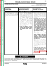
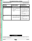
Engine will not go to high idle when
attempting to weld or when the
auxiliary power is loaded. Welding
output and auxiliary power output
is normal when Idler switch is in the
“HIGH” position.
1. Make sure the welding cables
and connections are tight.
2. Automatic idler may not func-
tion if the auxiliary power is
loaded to less than 150 watts.
1. Check for broken or faulty con-
nections in the sensing leads
(#254 and #254A). Make sure
their connections are tight at
the work output terminal and
also at the Polarity switch. See
Wiring Diagram.
2. Check lead #3 making sure it is
looped through the current sen-
sor on the printed circuit board.
3. The printed circuit board may
be faulty. Replace.