


Return to Section TOC Return to Section TOC Return to Section TOC Return to Section TOC
Return to Master TOC Return to Master TOC Return to Master TOC Return to Master TOC
OPERATION
B-5 B-5
RANGER 9 RANGER 9
AC
DC+
DC-
LINCOLN
ELECTRIC
RANGER 9
WARNING
RANGE
175
125
90
70
50
16 to 25
225 AC
210 DC
1
2
3
4
5
10 max
9
8
7
6
3
2
1
7
8
CHOKE
AUTO
HIGH
IDLER
START
RUN
STOP
9
11
54 6
1012 13
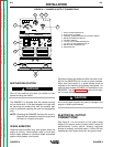
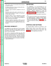
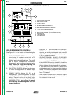
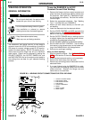
FIGURE B.1 – OUTPUT PANEL CONTROLS
1. OUTPUT RANGE SELECTOR
2. FINE OUTPUT CONTROL
3. POLARITY SWITCH
4. CONTROL AT WELDER/REMOTE CONTROL SWITCH
5. WELDING TERMINALS ALWAYS ON/
WELDING TERMINALS REMOTELY CONTROLLED SWITCH
6 WIRE FEEDER POWER CIRCUIT BREAKER
7. 115 VOLT, 20 AMP RECEPTACLES (2)
8. 115/230 VOLT, 50 AMP RECEPTACLE
9. WELD OUTPUT TERMINAL (TO WORK)
10. WELD OUTPUT TERMINAL (TO ELECTRODE HOLDER)
11. GROUND STUD
12. 14 PIN AMPHENOL
13. 6 PIN AMPHENOL
WELDER/GENERATOR CONTROLS
See Figure B.1 for the location of the following fea-
tures:
1. OUTPUT RANGE SELECTOR: Selects continuous
current output for constant current stick or TIG
applications (blue settings) and constant voltage
wire feed applications (red settings). The amper-
ages on the dial correspond to the maximum
amperages for each corresponding range setting.
Never change the range switch setting while
welding since this could damage the switch.
2. FINE OUTPUT CONTROL: Allows fine adjustment
of current or voltage within the selected output
range.
3. POLARITY SWITCH: Selects DC+, DC- or AC
welding output. Color codings aid in the proper
selection of stick (blue) or wire feed (red) polarity
setting. The color setting of the polarity switch
must match the color setting of the OUTPUT
RANGE SELECTOR. Never change the polarity
switch setting while welding since this could
damage the switch.
4. CONTROL AT WELDER/REMOTE CONTROL
SWITCH: Allows the operator to control welding
output at the welding control panel or at a remote
station. Remote connections are made at the 6 pin
or 14 pin amphenol connector.
5. WELDING TERMINALS ALWAYS ON/WELDING
TERMINALS REMOTELY CONTROLLED SWITCH:
Allows control of the RANGER 9 output contactor.
In the ALWAYS ON position, the switch closes the
output contactor, and welding begins when an arc
is struck between the electrode and the workpiece.
In the REMOTELY CONTROLLED position, the
switch places control of the contactor at the wire
feeder. The contactor closes when the wire feeder
gun trigger or amptrol switch closes and opens
when it is released.
6. WIRE FEEDER POWER CIRUIT BREAKER: Opens
the wire feeder circuit and disables the feeder if a
fault is detected in the circuit.