


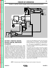
BATTERY, STARTER, ENGINE,
ROTOR, STATOR, AND IDLER
SOLENOID
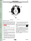
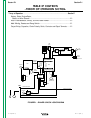
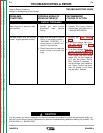
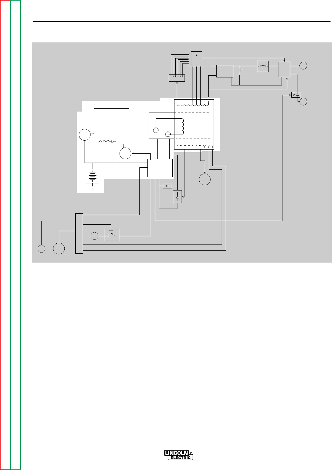
The 12VDC battery powers the starter motor. When
the engine is started and running, the battery circuit
voltage is fed, through the printed circuit board, to the
rotating field coil in the rotor via a brush and slip ring
configuration. This excitation (“flashing”) voltage mag-
netizes the rotor lamination. The rotor is mechanically
coupled to the engine. This rotating magnet induces a
voltage in the stationary windings of the main alterna-
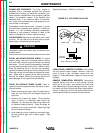
tor (stator). Four separate and isolated windings are
incorporated in the stator lamination assembly. Each
winding set has a different number of turns producing
different magnitudes of AC output voltages. The four
windings are the weld winding, the auxiliary power
winding, the field feedback winding, and the auxiliary
power winding for wire feeders. The field feedback
winding provides rotor current during machine opera-
tion. The output of the RANGER 9 is dependent on
two criteria: the engine RPM and the amount of current
in the rotor winding.
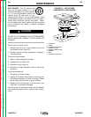
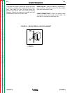
The flywheel alternator, located on the engine, supplies
“charging” current for the battery circuit. The battery
circuit provides power for the printed circuit board and
also for the idler solenoid. The idler solenoid is
mechanically connected to the engine throttle linkage.
If no current is being drawn from the RANGER 9, the
printed circuit board activates the idler solenoid, which
then brings the engine to a low idle state. When out-
put current is sensed, either weld or auxiliary, the print-
ed circuit board deactivates the idler solenoid, and the
engine returns to high RPM.
THEORY OF OPERATION
E-2 E-2
RANGER 9 RANGER 9
Return to Section TOC Return to Section TOC Return to Section TOC Return to Section TOC
Return to Master TOC Return to Master TOC Return to Master TOC Return to Master TOC
WORK
TERMINAL
OUTPUT
CONTACTOR
ELECTRODE
TERMINAL
POLARITY
SWITCH
CHOKE
PART OF
RANGE
SWITCH
CAPACITORS
OUTPUT
RECTIFIER
BRIDGE
AC
AC
RANGE
SWITCH
REACTOR
STATOR
ROTOR
MECHANICAL
ROTATION
ROTOR
SLIP
RINGS
IDLER
SOLENOID
ENGINE
STARTER
BATTERY
FLYWHEEL
ALTERNATOR
PRINTER
CIRCUT
BOARD
FIELD
CAPACITOR
115 & 230VAC
RECEPTACLES
FIELD
BRIDGE
CONTACTOR CLOSURE
BY-PASS
BOARD
CONTACTOR CLOSURE
REMOTE
SWITCH
OUTPUT
CONTROL
6 PIN
AMPHENOL
14 PIN
AMPHENOL
115VAC
42VAC
FIGURE E.2 – BATTERY, STARTER, ENGINE, ROTOR, STATOR AND IDLER SOLENOID
NOTE: Unshaded areas of Block Logic Diagram are the subject of discussion.