


WELDING OPERATION
GENERAL INFORMATION
• Do not touch electrically live parts or elec-
trodes with your skin or wet clothing.
• Do not breathe welding fumes or gases.
• Use ventilation or exhaust to remove
welding fumes from the breathing area.
• Keep flammable material away.
• Wear eye, ear, and body protection.
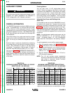
The RANGER 9 can deliver from 40 to 250 amps of
constant current for AC/DC stick welding or from 40 to
250 amps of constant voltage current for DC semiau-
tomatic wire feed welding. AC/DC TIG welding is pos-
sible across the entire range from 40 to to maximum
rated output. Output can be adjusted by setting the
POLARITY SWITCH, the OUTPUT RANGE dial, and
the FINE CONTROL dial on the output control panel to
the settings that are best for your selected welding
process.
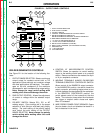
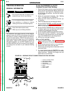
To use the RANGER 9 for AC/DC
Constant Current Stick Welding:
1. Remove the flange nuts from output terminals and
place the work and electrode welding cables over
the terminals. See Figure B.3. Replace and tight-
en the flange nuts securely. Be sure the connec-
tions are tight.
2. Select the appropriate electrode. See “Welding
Tips 1” included with your RANGER 9.
3. Attach the work clamp securely to the work you
are welding.
4. Insert the electrode into the electrode holder.
5. Set the IDLER CONTROL to AUTO and start the
gasoline engine. See ENGINE OPERATION in this
section of the manual.
6. Set the OUTPUT RANGE dial to a setting equal to
or slightly higher than the welding current recom-
mended for the electrode being used.
7. Set the POLARITY SWITCH to the desired polarity.
8. Set the FINE OUTPUT CONTROL. Use a setting
that results in the highest output at the lowest set-
ting of the RANGE switch for the application.
9. Strike an arc and begin welding.
After you finish welding:
1. Stop the gasoline engine. See ENGINE OPERA-
TION in this section of the manual.
2. Allow the electrode and work to cool completely.
3. Remove the work clamp from the work.
4. Remove any remaining piece of electrode from the
electrode holder.
5. If you are finished using the RANGER 9 for weld-
ing, disconnect the welding cables from the weld
output terminals. Reattach the flange nuts and
leave them on the terminals.
OPERATION
B-10 B-10
RANGER 9 RANGER 9
Return to Section TOC Return to Section TOC Return to Section TOC Return to Section TOC
Return to Master TOC Return to Master TOC Return to Master TOC Return to Master TOC
WARNING
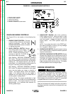
FIGURE B.3 – WELDING CIRCUIT CONNECTIONS FOR STICK WELDING
8
AC
DC+
DC-
LINCOLN
ELECTRIC
RANGER 9
WARNING
RANGE
175
125
90
70
50
16 to 25
225 AC
210 DC
1
2
3
4
5
10 max
9
8
7
6
1
CHOKE
AUTO
HIGH
IDLER
START
RUN
STOP
7
4
6
5
3
2
1. OUTPUT CONTROL PANEL
2. ELECTRODE CABLE
3. ELECTRODE HOLDER
4. ELECTRODE
5. OUTPUT TERMINALS
6. WORK
7. WORK CLAMP
8. WORK CABLE