


Return to Section TOC Return to Section TOC Return to Section TOC Return to Section TOC
Return to Master TOC Return to Master TOC Return to Master TOC Return to Master TOC
TROUBLESHOOTING & REPAIR
F-17 F-17
RANGER 9 RANGER 9
TROUBLESHOOTING GUIDE Observe Safety Guidelines
detailed in the beginning of this manual.
PROBLEMS
(SYMPTOMS)
POSSIBLE AREAS OF
MISADJUSTMENT(S)
RECOMMENDED
COURSE OF ACTION
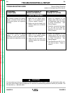
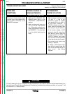
FUNCTION PROBLEMS
The output contactor does not pull
in when using a wire feeder with a
control cable connected to the
RANGER 9 amphenol.
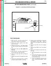
1. Make sure the WELDING TER-
MINALS switch (S6) is in the
“REMOTELY CONTROLLED”
position.
2. Install a jumper wire from pins
“D” to “C” on the 14 pin amphe-
nol. If the output contactor acti-
vates, the problem is external to
the RANGER 9. The wire feed-
er or the control cable may be
faulty.
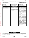
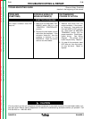
1. With the jumper installed in pins
“D” and “C” in the 14 pin
amphenol, check for 12VDC
from leads #224 (+) to #232 (-)
at the output contactor. If
12VDC is present and the con-
tactor does not activate, then
the contactor may be defective.
2. If the correct voltage is NOT
present in step #2, check from
lead #224 to ground (lead #5)
for the presence of 12VDC. If
12VDC is present, then check
the continuity of the lead #232A
to the idler printed circuit board.
3. The printed circuit board may
be faulty. Replace.
4. If 12VDC is NOT present from
lead #224 to ground (lead #5),
then check the #224 lead for an
open circuit. See Wiring
Diagram.
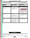
CAUTION
If for any reason you do not understand the test procedures or are unable to perform the test/repairs safely, con-
tact the Lincoln Electric Service Department for electrical troubleshooting assistance before you proceed. Call
216-383-2531 or 1-800-833-9353.