


Appendix 1 - 4
Appendix 1 Cable and Connector Specifications
MITSUBISHI CNC
Appendix 1-2 Cable connection diagram
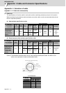
Appendix 1-2-1 Battery cable
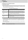
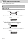
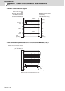
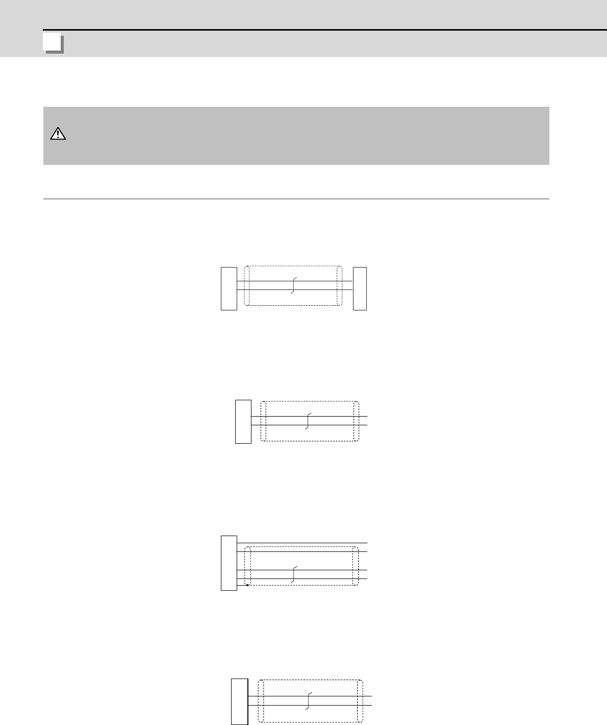
<DG22 cable connection diagram (Connection cable between drive unit and drive unit)>
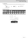
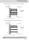
<DG23 cable connection diagram (Connection cable between drive unit and MDS-BTBOX-36)>
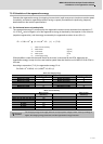
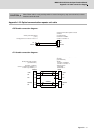
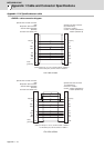
<DG24 cable connection diagram
(Connection cable for alarm output between drive unit and MDS-BTBOX-36)>
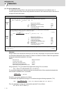
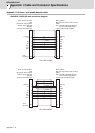
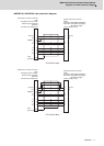
<DG25 cable connection diagram (Connection cable between drive unit and MDS-BTBOX-36)>
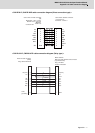
1. Take care not to mistake the connection when manufacturing the detector cable. Failure to observe
this could lead to faults, runaway or fire.
2. When manufacturing the cable, do not connect anything to pins which have no description.
CAUTION
1
2
1
2
BT
LG
BT
LG
0.2mm
2
Drive unit side connector
Connector: DF1B-2S-2.5R
Contact: DF1B-2428SCA
Drive unit side connector
Connector: DF1B-2S-2.5R
Contact: DF1B-2428SCA
(Hirose Electric)
(Hirose Electric)
1
2
BT
LG
BT
LG
0.2mm
2
: DF1B-2S-2.5R
: DF1B-2428SCA
Battery box side
Drive unit side connector
Connector
Contact
(Hirose Electric)
20
13
4
1
FG
DICOM
D11
P5
LG
+24V
DO(ALM)
+5V
LG
0.2mm
2
:10120-3000VE
:10320-52F0-008
0.2mm
2
0.2mm
2
Case
grounding
(DC power)
Drive unit side connector
Connector
Shell kit
Battery box side
(3M)
1
2
BT
LG
BT
LG
0.2mm
2
: DF3-2S-2C
: DF3-2428SCC
Battery box side
Drive unit side connector
Connector
Contact
(Hirose Electric)