


3 - 26
3 Function Specifications
MITSUBISHI CNC
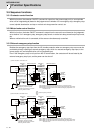
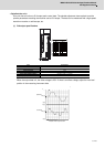
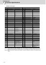
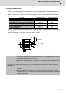
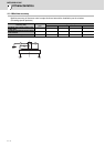
(Spindle control signal)
(Note 1) Control signal is bit output. Setting the No. of the table above to the data output(SP125, SP126),
and when the scale (SP127, SP128) is set to "0", the output is "0V" for bit 0, and "2.5V" for bit 1.
(Note 2) Refer to the section "Spindle control signal" in Instruction Manual for details on the spindle control
signal.
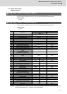
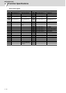
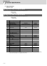
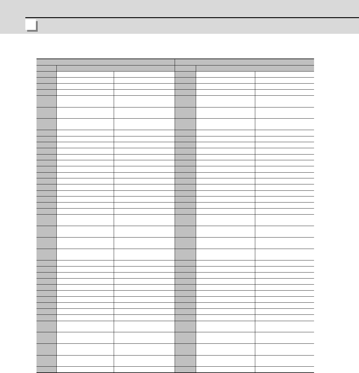
Spindle control input (NC to Spindle) Spindle control output (Spindle to NC)
No. Details No. Details
16384 Spindle control input 1-0 READY ON command 16480 Spindle control output 1-0 In ready ON
16385 Spindle control input 1-1 Servo ON command 16481 Spindle control output 1-1 In servo ON
16391 Spindle control input 1-7 Alarm reset command 16487 Spindle control output 1-7 In alarm
16392 Spindle control input 1-8
Torque limit 1 selection com-
mand
16488 Spindle control output 1-8 In torque limit 1 selection
16393 Spindle control input 1-9
Torque limit 2 selection com-
mand
16489 Spindle control output 1-9 In torque limit 2 selection
16394 Spindle control input 1-A
Torque limit 3 selection com-
mand
16490 Spindle control output 1-A In torque limit 3 selection
16492 Spindle control output 1-C In in-position
16495 Spindle control output 1-F In warning
16496 Spindle control output 2-0 Z phase passed
16499 Spindle control output 2-3 In zero speed
16503 Spindle control output 2-7 In external emergency stop
16432 Spindle control input 4-0
Spindle control mode selec-
tion command 1
16528 Spindle control output 4-0
In spindle control mode se-
lection 1
16433 Spindle control input 4-1
Spindle control mode selec-
tion command 2
16529 Spindle control output 4-1
In spindle control mode se-
lection 2
16434 Spindle control input 4-2
Spindle control mode selec-
tion command 3
16530 Spindle control output 4-2
In spindle control mode se-
lection 3
16436 Spindle control input 4-4 Gear changeover command 16532 Spindle control output 4-4
In gear changeover com-
mand
16437 Spindle control input 4-5 Gear selection command 1 16533 Spindle control output 4-5 In gear selection 1
16438 Spindle control input 4-6 Gear selection command 2 16534 Spindle control output 4-6 In gear selection 2
16545 Spindle control output 5-1 Speed detection
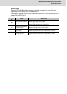
16459 Spindle control input 5-B
Minimum excitation rate 2
changeover request
16555 Spindle control output 5-B
In minimum excitation rate 2
selection
16460 Spindle control input 5-C
Speed gain set 2 changeover
request
16556 Spindle control output 5-C In speed gain set 2 selection
16461 Spindle control input 5-D
Zero point re-detection re-
quest
16557 Spindle control output 5-D
Zero point re-detection com-
plete
16462 Spindle control input 5-E Spindle holding force up 16558 Spindle control output 5-E
Spindle holding force up
completed
16559 Spindle control output 5-F In 2nd in-position